OWNER'S MANUAL LANGEVIN ELECTRO-OPTICAL LIMITER MANLEY LABORATORIES, INC. MANLEY LABORATORIES, INC. 13880 MAGNOLIA AVE. CHINO, CA. 91710 TEL: (909) 627-4256 FAX: (909) 628-2482 email: emanley @ netcom.com http://www.manleylabs.
CONTENTS SECTION PAGE INTRODUCTION 3 MAINS CONNECTIONS 4 OPERATION NOTES 5&6 FRONT PANEL 7 REAR PANEL 8 TROUBLE SHOOTING 9 & 10 INTERNAL ADJUSTMENTS 11 SPECIFICATIONS 12 WARRANTY 13 WARRANTY REGISTRATION 14
INTRODUCTION THANK YOU!... for choosing the Langevin Stereo Electro-Optical Limiter. This Limiter follows in the tradition of the vintage LA-3A Leveling Amplifier using a passive electro-optical device to control gain. The advantage of a passive device is that it eliminates the need to push the music through many transistors and / or ICs as would be the case in a VCA based Limiter. Also like the LA-3A, the Langevin utilizes a minimalist discrete transistor line amplifier for make-up gain.
MAINS CONNECTIONS Your Limiter has been factory set to the correct mains voltage for your country. The voltage setting is marked on the serial badge, located on the rear panel. Check that this complies with your local supply. Export units for certain markets have a moulded mains plug fitted to comply with local requirements. If your unit does not have a plug fitted the coloured wires should be connected to the appropriate plug terminals in accordance with the following code.
OPERATION NOTES The Langevin Electo-Optical Limiter follows certain traits and traditions established by the UREI LA-3A and similar levelling amplifiers. These traits can be divided into two aspects - electronic and operation. The electronic concept is simple and rather clean. Use the audio to light up LEDs which shine onto photo-resistors. These photo-resistors in combination with a fixed resistor simply act as a voltage divider to attenuate the signal.
The slope or ratio is also difficult to simulate. The initial ratio is low and becomes higher with more gain reduction until the leds light up fully and further reduction is not easy. This upper limit of reduction is in the area of 20 dB or at the bottom of the GR meter where the ratio becomes low again but this would be a severe setting that few engineers could use. Distortion becomes audible at very deep limiting.
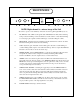
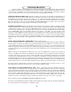
FRONT PANEL F G A B C D E E D C B A H NOTE: Right channel is a mirror image of the Left We do this to preserve exact similarity of the audio electronics (path length, PCB layout, etc) A IN / BYPASS. Audio still flows through the tubes in BYPASS but at Unity Gain. Switching to IN provides the Limiting controls and functions. Use this switch to verify that the limiting is not messing up the original sound but enhancing it or at least levelling the volume. B REDUCTION.
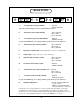
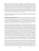
REAR PANEL A B D C F E K J I G A 1/4" INPUT (BALANCED) (RIGHT) B XLR INPUT (BALANCED) (RIGHT) C 1/4" OUTPUT (UNBALANCED) (RIGHT) D XLR OUTPUT (BALANCED) (RIGHT) E IEC MAINS CONNECTOR Standard IEC mains connector for 50 /60 Hz AC. F MAINS FUSE Replace with only a 1 Amp slo-Blo fuse.
TROUBLE-SHOOTING There are a number of possible symptoms of something not quite right, some may be interfacing, others we will touch on as well. The preceding page shows that all the inputs and outputs of the Electro-Optical Limiter are unbalanced. No need to panic. We have sold hundreds of these units and less than 1% ever had a problem with hum or interfacing to balanced consoles or other gear. However if you suspect a problem the following paragraphs should help.
HUM - Let's assume it knows the words. Once again - several possibilities - several cures. Most likely it is a ground loop. The two most common procedures are: try a 3 pin to 2 pin AC adapter (about a dollar at the hardware store) which is better than messing up the power cable by bending the ground pin until it breaks off. Method two - cutting the shield on one side of the cable. This is usually done at every female XLR to "break" all loops. You may get a loop simply from the rack.
INTERNAL ADJUSTMENTS 1 5 4 8 2 1) 9 6 7 10 3 +36 Volt DC adjust with meter from ground to resistor marked by arrow. Check this first and adjust if needed. It is the power supply regulator adjustment. Now for the audio .... You will have to start out by setting front panel controls to these settings. BYPASS mode, SEP ( LINK OFF ), REDUCTION controls counter clockwise (MIN), GAIN to 1:00 or unity, Balance at 12:00. The top will need to be open.
SPECIFICATIONS Langevin Electro- Optical Limiter Maximum Input (Bypass through Line Amplifier) +30 dBv (with Limit "IN" the maximum is entirely variable) Maximum Output +30 dBv Headroom (referenced to +4 dBv) 26 dB Frequency Response: 10 Hz to 70 kHz +/- 0.5 dB THD & Noise (1kHz @ +4 dBm) .
WARRANTY All Manley Laboratories equipment is covered by a limited warranty against defects in materials and workmanship for a period of 90 days from date of purchase to the original purchaser only. A further optional limited 5 year warranty is available to the original purchaser upon proper registration of ownership within 30 days of date of first purchase.
WARRANTY REGISTRATION We ask that you please fill out this registration form and send the bottom half to: MANLEY LABORATORIES REGISTRATION DEPARTMENT 13880 MAGNOLIA AVE. CHINO CA, 91710 Registration entitles you to product support, full warranty benefits, and notice of product enhancements and upgrades. You MUST complete and return the following to validate your warranty and registration. Thank you again for choosing to use Manley Laboratories. MODEL ____________________ SERIAL No.