MANLEY LABORATORIES, INC. OWNER'S MANUAL MONO "VARIABLE-MU" LIMITER / COMPRESSOR 5670 MODELS MANLEY LABORATORIES, INC. 13880 MAGNOLIA AVE. CHINO, CA. 91710 TEL: (909) 627-4256 FAX: (909) 628-2482 email: emanley@netcom.
CONTENTS SECTION PAGE INTRODUCTION 3 MAINS CONNECTIONS 4 INSTALLATION 5 FRONT PANEL 6 REAR PANEL 7 OPERATIONAL NOTES 8 TECHNICAL NOTES 9 TYPICAL SETTINGS 10 SERVICE ADJUSTMENTS 11 SPECIFICATIONS 12 WARRANTY 13 WARRANTY REGISTRATION 14
INTRODUCTION THANK YOU!... for choosing the Manley Laboratories Mono Variable-MU Limiter Compressor Amplifier. The heart of this limiter is the unique 5670 variable-mu vacuum tube which can handle a widely varying range of input signals in a rapid-acting manner without introducing harmonic distortion. This limiting circuitry was designed by David Manley over thirty years ago. Our current version of this 1960s design combines that classic sound with the precise cleanliness of modern componentry.
MAINS CONNECTIONS Your unit has been factory set to the correct mains voltage for your country. The voltage setting is marked on the serial badge, located on the rear panel. Check that this complies with your local supply. Export units for certain markets have a moulded mains plug fitted to comply with local requirements. If your unit does not have a plug fitted the coloured wires should be connected to the appropriate plug terminals in accordance with the following code.
INSTALLATION Please refer to the REAR PANEL section for a full layout of the rear panel of your Mono limiter compressor. 1. Set the voltage change-over switch on the back of the unit to the voltage you are using. 2. Be certain that the unit has a 1 Amp SLO-BLO (120 Volt operation) fuse. 3. Connect the input signal(s) to the 3 pin female XLR's on the rear panel.
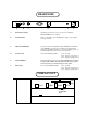
FRONT PANEL INPUT IN THRESHOLD RECOVERY LIMIT SLOW ATTACK OUTPUT POWER MANLEY • MED 10 dB LIMITER COMPRESSOR MONOBLOCK • BYPASS COMPRESS MIN A B C MAX METER D E F FAST HANDCRAFTED IN CHINO, CALIFORNIA U.S.A. SLOW FAST G H I J A IN / BYPASS Switched in bypass mode, (down position) all effects of the limiting circuitry are bypassed and will not affect the audio signal. In the bypass mode , the audio signal passes from the input directly to the output. B.
REAR PANEL A B C D E F A IEC MAINS SOCKET Standard 3 pin AC mains socket. See the section MAINS CONNECTIONS for more details. B FUSE HOLDER Houses a standard 1 Amp SLO-BLO fuse. Replace only with the same type and size. C GROUND TERMINALS Separate terminals for CIRCUIT (audio) GROUND and CHASSIS (AC) GROUND. Typically these should be joined with the flat jumper supplied. Hum problems or various grounding options are available by different connections to these terminals.
OPERATION NOTES The "MANLEY MONO VARIABLE MU LIMITER - COMPRESSOR" is designed for multiple purposes. The unit can be used as half of a stereo pair by using the link terminal on the back. It can be used as a balanced line amp capable of 30 db! of gain and as a pre-amp for low level signals. Watch your levels with this unit as UNITY GAIN is not with all knobs pointing up. With higher input gain settings the unit can be used to create tube distortion if desired.
TECHNICAL NOTES SWITCHING ON The power switch is located on the right hand corner of the front panel. Flip the switch up to turn on the Limiter Compressor and down to turn off. Do not do this up and down rapidly - could cause damage. TUBE LIFE As with all tubes, their quality degrades with age. This is due to cathode emission, a natural process found in all tubes. We recommend that you have your unit checked every 4-5 years, depending on usage.
SERVICE ADJUSTMENTS These are factory presets. These should only be altered after a re-tube. A METER (FRONT PANEL TRIM) - Set in Limit Mode 1. The LIMITER COMPRESSOR is factory calibrated and you should not re-adjust these trims unless you have re-tubed the unit or you suspect that the unit is in need of a "cal". The unit will need to be warmed up for at least an hour to adjust any of these trimmers. AC power fluxuations can affect the meter calibrations. 2.
SPECIFICATIONS Electronics Transformer Input, 3 dual triodes in balanced symmetrical variable mu circuit / line amp and Transformer Output per channel. Vacuum tube audio rectification for side chain. Custom Meters, Attenuators, etc. Input and output transformers designed by David Manley and wound inhouse at Manley Lab's magnetics department.
WARRANTY All Manley Laboratories equipment is covered by a limited warranty against defects in materials and workmanship for a period of 90 days from date of purchase to the original purchaser only. A further optional limited 5 year warranty is available to the original purchaser upon proper registration of ownership within 30 days of date of first purchase.
WARRANTY REGISTRATION We ask that you please fill out this registration form and send the bottom half to: MANLEY LABORATORIES REGISTRATION DEPARTMENT 13880 MAGNOLIA AVE. CHINO CA, 91710 Or you can FAX this page in: (909) 628-2482 Registration entitles you to product support, full warranty benefits, and notice of product enhancements and upgrades. You MUST complete and return the following to validate your warranty and registration. Thank you again for choosing to use Manley Laboratories.