0 dB LIMITING HI +10 0 MIN 0 MAX -10kHz LIMIT z-1kHz -12 dB RELEASE +12 UENCY c -6 o dB OUTPUT GAIN +4 r e R c o FAST O/P 2 O/P 1 LIMITER MAX e REFERENCE CHANNEL STRI REFERENCE CHANNEL STRIP SLOW r GR EQ M DIRECT OUT 1 OWNER’S MANUAL MAIN OUT 2 EQ TUBE STAGE INSERT JACK TIP: SEND RING: RETURN SLEEVE: GROUND INSERT OUTPUT GAIN FET BRICKWALL LIMITER DIRECT OUTPUT (1) c o r e REFERENCE CHANNEL STRIP LINE INPUT MIC INPUT XLR PINOUT PIN1: SHIELD/GROUND PIN2: HO
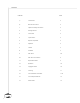
Contents CHAPTER i) c 1 o r e PAGE Introduction 2 ii) Manual Conventions 2 1. Important Safety Instructions 3 2. Getting Started 3 3. Front Panel 4 4. Input Section 4 5. Optical Compressor 5 6. Equalizer 5 7. Limiter 6 8. VU Meter 6 9. Rear Panel 7-8 10. Rear Panel Connections 9 11. Operational Notes 9 12. Questions 10 13. Copyright Notice 10 14. Servicing 11 15. Core Calibration Procedure 11-12 16. Curves & Specifications 13 17.
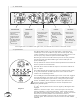
i) An Introduction To The Manley Core Reference Channel Strip Thank you for selecting the Manley CORE. This unit combines a high quality vacuum tube microphone preamplifier, an ELOP® Compressor, an EQ section and a fast FET Brickwall Limiter. Musical. Flexible. Forgiving. These three concepts were my main goals in designing the CORE channel strip. To give the musician tools he or she really needs, without needless complication.
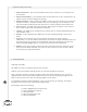
1. Important Safety Instructions 1. Water and Moisture – Do not use The CORE near any source of water or in excessively moist environments. 2. Object and Liquid Entry – Care should be taken so that objects do not fall, and liquids are not spilled, into the enclosure through the openings. 3. Heat & Ventilation – When installing The CORE in a rack or any other location, be sure there is adequate ventilation. Improper ventilation will cause overheating, and can damage the unit.
3.
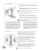
5. ELOP® Compressor ® The ELOP Compressor utilizes our famous circuit topology as ® ® found in the VOXBOX , and is also similar to the ELOP and SLAM limiters. The COMPRESSION (Threshold) control determines at what level the compressor begins to act. Clockwise rotation makes the compressor reduce the signal. ATTACK COMPRESSION SLOW With the meter in the “GR” position, the amount of gain reduction can be displayed. (Refer to Diagram 6, pg.
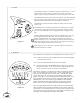
. Limiter The FET output limiter is a powerful, high-ratio, peak limiter. It can be used for many creative effects, as well as for setting a maximum output ceiling to avoid overloading the next piece of gear in the chain. The LIMITING knob controls the amount of limiting. The LIMIT LED lights when the signal crosses the threshold, and goes off when the signal is both below the threshold and the release time is completed.
9. Rear Panel INPUT LEVEL MIC 120Hz HI 48V 180 MIC LINE FLAT LOW PHANTOM 0 HANDCRAFTED IN CALIFORNIA USA DIRECT INP DIRECT IN MIC IN MAINS VOLTAGE SHOWN ON SERIAL TAG WARNING: TO REDUCE THE RISK OF FIRE OR ELECTRIC SHOCK, DO NOT EXPOSE THIS UNIT TO RAIN OR MOISTURE CAUTION: RISK OF ELECTRIC SHOCK. DO NOT OPEN. REFER SERVICING TO QUALIFIED PERSONNEL ONLY. PHASE OPERATIONAL BLOCK DIAGRAM INSTRUMENT IN DI STAGE ® HP FILTER ATTENUATOR COMPRESSOR LINE IN LINE STAGE MANLEY LABORATORIES INC.
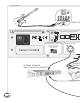
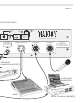
Diagram 7 INPUT (FRONT PANEL) MAIN OUT 2 DIRECT OUT 1 EQ TUBE STAGE FET BRICKWALL LIMITER INSERT JACK TIP: SEND RING: RETURN SLEEVE: GROUND OUTPUT GAIN DIRECT OUTPUT (1) c o r e REFERENCE CHANNEL STRIP LINE INPUT MIC INPUT XLR PINOUT PIN1: SHIELD/GROUND PIN2: HOT/POSITIVE PHASE PIN3: LOW/NEGATIVE PHASE INSERT L PROCESSOR R COMPRESSOR OR EFFECTS DIGITAL AUDIO WORKSTATION MIXER DIGITAL TO ANALOG CONVERTER 8
. Rear Panel Connections From Right to Left: MIC INPUT: This is a transformer balanced, microphone input to the preamplifier. The pinout is PIN 1: Ground, PIN 2: HOT (+), PIN 3: COLD(-). ! All pins must be driven. DO NOT “float” PIN 2 or PIN 3. LINE INPUT: An electronically-balanced, line-level input. The pinout is PIN 1: Ground, PIN 2: HOT (+), PIN 3: COLD(-). An unbalanced source can be connected with PIN2 or 3 grounded. Unused pins can be grounded.
12. Questions Q: “Where's the -20dB pad switch?” Because the input attenuator precedes the tube gain stage, the input level control acts as a variable pad. It can be used to either reduce the level of a hot input signal, or to simply set the overall gain of the preamp. Q: “Sometimes I hear distortion in the peak limiter!” To allow for maximum creativity, the release time of the limiter was intentionally allowed to operate over a wide range.
14. Servicing TUBE LOCATION 6922 12AX7WA Diagram 8 CALIBRATION TRIM POT LOCATION GR-ZERO GR-METER GR-AUDIO LIM CV VR9 VR15 VR11 VR6 LIM REF V OP1 ZERO VU VR12 VR16 2 Amp Slow-Blow (T) 20mm Ceramic FUSE Diagram 9 TEST POINT LOCATION 15. Core Calibration Procedure c 11 o r The CORE requires calibration for 3 sections of its circuitry: I) VU METER- Adjust: +4dBu (1.
i) CALIBRATION OF VU METER: 1- Feed a balanced sine tone @ 1 KHz, +4dBu (1.228V RMS) from an audio tone generator/oscillator into the LINE INPUT XLR. 2- Use your audio analyzer and/or, set your voltmeter to read volts AC and put it at the output of XLR “OP1”. Star tbringing up the Input level attenuator until you have +4dBu (1.228V RMS) at the output XLR “OP1”. This will be the same level as the input signal from oscillator (unity gain) 3- Use the VU meter select switch to read “OP1”.
16.
c o r FLAT LINE 48V LOW PHANTOM HI 0 180 MIC 48V MIC COMPRESSOR SLOW FAST BYPASS FAST FLAT LINE LOW PHANTOM HI 0 180 MIC NOTES COMPRESSOR SLOW FAST BYPASS SONG RELEASE MAX IN FAST INSTRUMENT / TRACK MIN SLOW ARTIST DIRECT IN HANDCRAFTED IN CALIFORNIA USA 120Hz MIC COMPRESSION ATTACK MIC NOTES RELEASE MAX IN SONG MIN SLOW INSTRUMENT / TRACK INPUT LEVEL ATTACK COMPRESSION ARTIST DIRECT IN HANDCRAFTED IN CALIFORNIA USA 120Hz MIC INPUT LEVEL -12 -12 dB
0 INPUT LEVEL ATTACK LOW COMPRESSION 120Hz HI 48V SLOW 180 -10 dB 0 FAST 1kHz-10kH IN MIC BYPASS FLAT LOW PHANTOM 0 MIN MAX -12 dB 100Hz-1kH +12 FREQUENC DCRAFTED IN CALIFORNIA USA RELEASE SLOW FAST DIRECT IN COMPRESSOR MIN EQ MAINS VOLTAGE SHOWN ON SERIAL TAG WARNING: TO REDUCE THE RISK OF FIRE OR ELECTRIC SHOCK, DO NOT EXPOSE THIS UNIT TO RAIN OR MOISTURE CAUTION: RISK OF ELECTRIC SHOCK. DO NOT OPEN. REFER SERVICING TO QUALIFIED PERSONNEL ONLY.