MANLEY REFERENCE MICROPHONES Reference Cardioid Reference Mono Gold Reference Stereo Gold OWNER’S MANUAL rev9-2-11cd
CONTENTS SECTION PAGE INTRODUCTION 3 POWER SUPPLY 4 MICROPHONE CONTROLS 5 GENERAL NOTES 6 MAINS CONNECTIONS 7 TROUBLESHOOTING 8 STEREO GOLD ADDENDUM 9 SPECIFICATIONS 10 VOLTAGE CONVERSION 11
INTRODUCTION THANK YOU!... ...for choosing a Manley Laboratories REFERENCE SERIES MICROPHONE. This manual covers the following models: Reference Cardioid, Reference Mono Gold, and Reference Stereo Gold. GENERAL NOTES Manley microphones will beat all others on grounds of sheer naturalness of sound without coloration or perceivable sonic signature. The design is optimized for extremely wide frequency response and exceptionally accurate transient response.
The open mesh design of the mic allows all the highs to reach the capsule unimpared and allows the engineer to choose if, when and how much pop screen is appropriate. Vocal “pops” may distort the capsule without a pop screen. Air movement and wind can overload a good capacitor mic capsule much easier than loud levels.We strongly recommend a good 2 layer nylon pop screen with this mic on close vocals. A built in foam screen needs built in HF boost - not here.
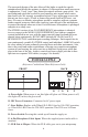
MICROPHONE CONTROLS A: PATTERN SELECT CONTROL (GOLD MODELS) OMNI FIGURE 8 CARDIOID This control provides the user with a choice of any typical polar pattern. Many high quality condenser microphones give the user 3 or 4 patterns only; we chose to provide you with an infinite number of patterns via this control. For example, a setting between the “heart shaped” CARDIOID and FIGURE 8 will result in “SUPER-CARDIOID” and “HYPER-CARDIOID” patterns.
GENERAL NOTES CONNECTIONS MONO REFERENCE GOLD & REFERENCE CARDIOID MODELS - connect 6-pin cable (supplied with mic) between PSU and mic. Audio comes from separate 3 pin XLR on the PSU. STEREO REFERENCE GOLD MODEL - carefully connect the 4 pin power cables to the mic and power supply. Line up the groove and ridge of these connectors to prevent accidental damage. Next connect a known good mic cable to the power supply, and you’re ready to record.
MAINS CONNECTIONS Your REFERENCE MICROPHONE Power Supply has been factory set to the correct mains voltage for your country. The voltage setting is marked on the serial badge, located on the underside of the power suppy. Check that this complies with your local supply. Export units for certain markets have a moulded mains plug fitted to comply with local requirements.
TROUBLESHOOTING NO POWER, NO INDICATORS, NADA - Probably something to do with AC power. Is it plugged in? Murphy’s Law. Check the fuse on the back panel. A blown fuse often looks blackened inside or the little wire inside looks broken. A very blackened fuse is a big hint that a short occured. Try replacing the fuse with a good one of the same value and size. If it blows too then prepare to send the unit back to the dealer or factory for repair.
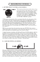
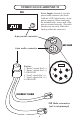
STEREO GOLD ADDENDUM PSU Power Supply: Instead of a six-pin power/audio connector, the Stereo Gold mic’s PSU holds merely a 4-pin power connector. When connecting the included cable, ensure each of the pins are oriented correctly. (The cable should screw on easily if the tab is lined up within the connector.) 4-pin power connector MIC BASE 6-pin audio connector Pin Out: 1. “Rotate” capsule Pin 2 (+) 2. “Rotate” capsule Pin 3 (-) 3. (GROUND) 4. “Fixed” capsule Pin 3 (-) 5. “Fixed” capsule Pin 2 (+) 6.
SPECIFICATIONS REFERENCE GOLD SERIES CAPSULE TYPE: POLAR PATTERNS: DIAPHRAGM SIZE: DIAPHRAGM THICKNESS: FREQUENCY RESPONSE: MAXIMUM INPUT SPL: SENSITIVITY: AMPLIFIER TYPE: ACTIVE COMPONENTS: OUTPUT TYPE : OUTPUT POLARITY: AMPLIFIER DISTORTION: AMPLIFIER NOISE: BODY: DUAL LARGE DIAPHRAGM CAPACITOR CONTINUOUSLY VARIABLE (omni through cardioid through Figure 8) 1 INCH; 1.
VOLTAGE CONVERSION All servicing described below should be referred to a qualified technician. 1. Unplug PSU from wall and disconnect microphone cable(s). Let sit for at least 15 minutes to let the capacitors discharge. 2. Remove PSU cover, held in place by 4 x philips screws. 3. Observe the jumpers located on PCB0718B, and the accompanying diagram printed on the PCB itself. 4.