Line Trimmer “E” System Owners Manual and Safety Instructions © 2006 Mantis, Div. of Schiller-Pfeiffer Inc. All Rights Reserved.
Table of Contents Important Information Assembly Instructions . . . . . . . . . . . . . . .5 Introduction . . . . . . . . . . . . . . . . . . . . . . . . . . . .1 Special Safety Information . . . . . . . . . . . . . . . .1 Operation . . . . . . . . . . . . . . . . . . . . . . . . . .6 Maintenance . . . . . . . . . . . . . . . . . . . . . . .8 Safety and Warnings Safety Decals . . . . . . . . . . . . . . . . . . . . . . . . . .2 General Safety Rules . . . . . . . . . . . . . . . . . . . .
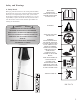
Safety and Warnings A. Safety Decals Please pay particular attention to the warning and information decals found on various parts of this Line Trimmer Attachment unit. They are an important part of the safety system. These decals must be replaced in time due to abrasion, etc. It is your responsibility to replace the decals when they become hard to read. The location of these decals and their part numbers for ordering are shown below.
General Safety Rules Never lean over the rotating cutting head. Rocks or other debris could be thrown into eyes and face and cause serious personal injury. WARNING WHEN USING ELECTRIC TOOLS, BASIC SAFETY PRECAUTIONS, INCLUDING THE FOLLOWING, SHOULD ALWAYS BE FOLLOWED TO REDUCE THE RISK OF FIRE, ELECTRIC SHOCK AND PERSONAL INJURY. Pay particular attention to all sections regarding safety. Read and understand all these instructions before operating this product and save these instructions.
18. Check damaged parts. Before further use of the tool, a guard or other part that is damaged should be carefully checked to determine that it will operate properly and perform its intended function. Check for alignment of moving parts, free running of moving parts, breakage of parts, mounting and any other conditions that may affect its operation.
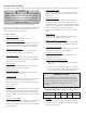
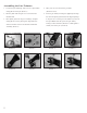
Assembling the Line Trimmer 1. Locate and open sealed bag with 3 screws, 3 split washers, clamp plate #2 and L-pin. (Picture 1) 4. Place gear case cover #4 onto the gear shaft. (Pictures 4 and 5) 2. Remove plastic tube and gear case cover #4 from the 5. Lock the gear shaft by inserting the supplied pin through threaded shaft. the slot in the plastic guard and into the aligned openings in the gear case cover and gear case (Pictures 6). Screw in 3.
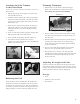
Attaching the Line Trimmer to the Power Head No tools are required to attach the Line Trimmer to the power head assembly. Trimming Techniques 1. With both hands on the handles, push lockout trigger button with your thumb first, and then squeeze trigger. Start cutting when spool rotates at full RPM. 1. Pull the spring pin up on the adapter of the power head shaft assembly. (Picture 9) Picture 13 2.
Refilling the Trimming Line WARNING DANGER NEVER REPLACE OR ADJUST THE TRIMMING LINE WHILE MOTOR IS RUNNING! DISCONNECT POWER CORD FROM THE POWER SOURCE. Holes Approx. 6" longer Picture 14 Picture 15 Picture 16 Picture 17 Replacement spools can be ordered through your Mantis dealer. 1. For safety reasons, do not use metal reinforced line. 2. For replacement use 0.095" dia line. The spool is capable to hold approximately 20' long line. 3.
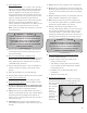
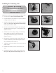
Maintenance Area Maintenance procedure Frequency Spline male/female connection of the inner drive shaft Pull Loosen Remove Inspect/Lubricate 1. Remove center screw, and loosen up other two as shown on the diagram (left). 20-25 Hrs 2. Pull the shaft from the gear housing. 3. Pull and clean internal shaft. 4. Lubricate. Lubricate 5. Re-install the drive shaft. Gear case Inspect/Clean debris Remove plug and check level of grease. Add grease.
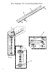
Line Trimmer “E” System Exploded View 40 38 39 37 36 14 16 12 13 1 15 1 28 2 18 29 17 35 3 4 41 42 5 30 6 32 31 7 27 8 26 43 9 25 44 24 23 19 22 21 9 20 33 34
Line Trimmer “E” System Parts List KEY # DESCRIPTION PART # QTY 1 GEAR CASE-ASS’Y 331186 1 2 GEAR CASE 331187 3 BEARING 609 4 GEAR 5 KEY # DESCRIPTION PART # QTY 24 SPRING 331204 1 1 25 PLATE 331205 1 331146 1 26 SPOOL HOLDER 331206 1 331188 1 27 CENTER INSERT 331207 1 MAIN GEAR HOUSING SHAFT 331189 1 28 GUARD ASS'Y WITH CLAMPING PLATE 331208 1 6 BEARING 6201 331190 1 7 SNAP RING 331191 1 29 GUARD SUB-ASSEMBLY 331209 1 8 SEAL 331192 1 30 CLAMPI
2 YEAR LIMITED SERVICE & WARRANTY POLICY FOR LINE TRIMMER ATTACHMENT MANTIS extends this limited warranty against defects in material and workmanship for a period of two years from the date of purchase, to the first retail purchaser and each subsequent owner during the warranty period. This warranty covers all portions of the Mantis Line Trimmer Attachment.