Power Head E System Moteur E-System E-System-Getriebekopf Owners manual and safety instructions Manuel d’utilisation et consignes de sécurité Benutzerhandbuch und Sicherheitshinweise © 2006 Mantis, Div. of Schiller-Pfeiffer Inc. All Rights Reserved. © 2006 Mantis, Division de Schiller Pfeiffer Inc. Tous droits réservés. © 2006 Mantis, Division von Schiller Pfeiffer Inc. Alle Rechte vorbehalten.
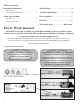
Table of contents Important information Specifications . . . . . . . . . . . . . . . . . . . . . . .4 Introduction . . . . . . . . . . . . . . . . . . . . . . . . . . . .1 Special Safety Information . . . . . . . . . . . . . . . .1 Assembly instructions . . . . . . . . . . . . . . . .4 Parts explosion . . . . . . . . . . . . . . . . . . . . .5 Safety and warnings Safety decals . . . . . . . . . . . . . . . . . . . . . . . . . . .2 General safety rules . . . . . . . . . . . . . . . . . . . . .
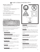
SAFETY SYMBOLS IDENTIFICATION What the symbols mean: 1. Read the instructions. 1 2 3 4 2. Do not expose to rain. 3. Remove plug from main (electric power source) immediately if cable is damaged or cut. 4. Double insulated. 5. Unit should be properly disposed. Service information contact If you have questions about any topic in this Manual, contact your local authorised Mantis dealer.
12. Disconnect tools. When not in use, before servicing and when changing accessories such as blades, bits and cutters. 13. Remove adjusting keys and wrenches. Form the habit of checking to see that keys and adjusting wrenches are removed from the tool before turning it on. 14. Avoid unintentional starting. Do not carry a plugged in tool with a finger on the switch trigger. Ensure switch is off when plugging in. 15. Use outdoor extension leads.
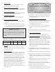
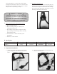
your footing, balance or control of the machine. While operating the machine always be sure of a safe and secure operating position especially when using steps or a ladder. Always be sure of your footing on slopes. WARNING – 35. Securing the extension cord. Bend the extension cord about 40 cm from the plug end. Push that bend through the oblong opening in the back of the handle. Then loop the bend under the cord retaining clips as shown.
c) Drive in the four screws supplied, starting with the bottom two screws. Do not tighten screws. d) Adjust handle location to your preference, and then tighten all screws. D. Brush Replacement Brush of the motor is replaceable. Brush has to be replaced after approximately 150 hours of use. The life of the brush depends on the use of the unit and may last much longer. Do not replace it yourself. Contact your local authorised Mantis dealer for a brush replacement.
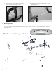
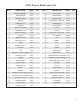
230V Power Head parts list KEY # DESCRIPTION PART # QTY 1 MOTOR ASSEMBLY 331298 1 2 MOTOR BRUSH 331253 3 BRUSH HOLDER 4 DESCRIPTION PART # QTY 31 INLAY (LEFT) 331277 1 2 32 WIRE JOINTER 331278 1 331254 2 33 POWER CORD 331302 1 HOLDER 331255 2 34 EXTENSION CORD CLIP 331280 1 5 SCREW ST2,9X10 331556 4 35 SCREW M5X35 331565 4 6 SHUTTER 331256 2 36 LOOP HANDLE 331281 1 7 REV CONTROLLER 331299 1 37 CLAMP 331282 1 8 SCREW ST3,5X13 331557 2 38 NUT
2 YEAR LIMITED SERVICE & WARRANTY POLICY FOR ELECTRIC POWER HEAD E SYSTEM MANTIS extends this limited warranty against defects in material and workmanship for a period of two years from the date of purchase, to the first retail purchaser and each subsequent owner during the warranty period. This warranty covers all portions of the Mantis E System Electric Power Head.
MANTIS 1028 Street Road Southampton , PA 18966 + (215) 355-9700 P/N 331705 Rev.