SA7x/6000 Cabinet Series Upgrade Installation Guide Order Number EK–SA7CK–IN–003 Digital Equipment Corporation Maynard, Massachusetts
First Revision, October 1989 Second Revision, April 1992 Third Revision, September 1992 The information in this document is subject to change without notice and should not be construed as a commitment by Digital Equipment Corporation. Digital Equipment Corporation assumes no responsibility for any errors that may appear in this document. Restricted Rights: Use, duplication, or disclosure by the U.S.
Contents Preface vii Chapter 1 SA70–CK and Upgrade Kits 1.1 1.2 1.3 Introduction . . . . . . . . . . . . . . SA70–CK Parts List . . . . . . . . Unpacking the SA70–LK/MK, Options . . . . . . . . . . . . . . . . . ........................... ........................... SA71–NK/PK, SA72–NK/PK, and ........................... . . . . . . . . . . . . . . . . . 1–1 . . . . . . . . . . . . . . . . . 1–3 SA73–NK/PK . . . . . . . . . . . . . . . . . 1–5 Chapter 2 Safety Precautions 2.1 2.2 2.3 Introduction .
3.8 3.7.2 Installing the Rear Clamping Assembly . . . . . . . . . . . . . . . . . . . . . . . . . . . . . 3.7.3 Installing the Digital Medallion . . . . . . . . . . . . . . . . . . . . . . . . . . . . . . . . . . . 3.7.4 Repositioning the SA7x Enclosure Operator Control Panel . . . . . . . . . . . . . . 3.7.5 Routing the SA7x Enclosure Cables . . . . . . . . . . . . . . . . . . . . . . . . . . . . . . . . Powering Up the Cabinet . . . . . . . . . . . . . . . . . . . . . . . . . . . . . . . . . . . . . . .
3–11 3–12 3–13 3–14 4–1 4–2 6–1 Repositioning Transition Board 1 . . . . . . . . . . . . . . . . . . . . . . . . . . . . . . . . . . . Attaching a Single SDI Cable to the SA7x and KDB50/KDM70 I/O Bulkhead . Attaching a Second SDI Cable to the SA7x and KDB50/KDM70 I/O Bulkhead Cabinet Control Panel and Power Controller . . . . . . . . . . . . . . . . . . . . . . . . . . Front Panel View of the SA7x Enclosure . . . . . . . . . . . . . . . . . . . . . . . . . . . . . Rear Panel View of the SA7x Enclosure . .
Preface This manual describes: • How to unpack the SA70–LK/MK, SA71–NK/PK, SA72–NK/PK, or the SA73–NK/PK options. • Safety precautions for Digital Services engineers working with the VAX 6000-series processor cabinet. • How to install SA70–LK/MK, SA71–NK/PK, SA72–NK/PK, or SA73–NK/PK enclosures into an existing, installed VAX 6000-series processor cabinet Intended Audience All Digital Services engineers installing an SA7x enclosure into a VAX 6000-series processor cabinet should read this manual.
Scope General information about the VAX 6000-series processor cabinet and field acceptance procedures is not contained in this manual. Refer to documentation for the VAX 6000-series cabinets for that information.
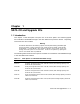
Chapter 1 SA70–CK and Upgrade Kits 1.1 Introduction This chapter a brief description and parts list of the SA7x options and related upgrade kits available as Embedded Storage in the VAX 6000 series processor cabinet. Unpacking instructions are also included. Warning Procedures described in the following chapters must be performed by qualified Digital Services engineers.
Table 1–1 (Cont.
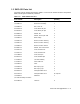
1.2 SA70–CK Parts List The SA70–CK kit contents are listed in Table 1–2. Be sure all contents of the kit are present before starting the installation procedure.
Table 1–2 (Cont.
1.3 Unpacking the SA70–LK/MK, SA71–NK/PK, SA72–NK/PK, and SA73–NK/PK Options The SA7x options are shipped in a packaging box. The SA70–CK kit are shipped in a separate package. Cut the shipping straps, open the top container, and unpack the option, as shown in Figure 1–1.
Figure 1–1: Unpacking the SA70 Enclosure CONTAINER MANUALS AND MOUNTING HARDWARE SA7x ENCLOSURE DESICCANT SHIPPING STRAPS CXO-2439B_S 1–6 SA70–CK and Upgrade Kits
Chapter 2 Safety Precautions 2.1 Introduction This chapter discusses hazards and safety precautions that the Digital Services engineer should be aware of before installing SA70–CK kit, SA70–LK/MK, SA71–NK/PK, SA72– NK/PK, and SA73–NK/PK options into the VAX 6000-series processor cabinet. Warning Only qualified Digital Services engineers should perform these procedures.
Chapter 3 Installing the SA70–CK Kit 3.1 Introduction This chapter describes the following: • How to power down the VAX 6000-series processor cabinet • How to install the SA7x (62X34-UA/UB) upgrade kits, which includes a front door with SA7x operator control panel (OCP) access, appropriate logo slug, and an H405 power controller.
Figure 3–1: Front View of the VAX 6000-Series Processor Cabinet FRONT DOOR KEY PIN FRONT DOOR KEY PIN OCP ACCESS PANEL 3–2 Installing the SA70–CK Kit GROUND STRAP CXO-2787A
Figure 3–2: Rear View of the VAX 6000-Series Processor Cabinet ESD PACKET ESD GROUND LUG H405 POWER CONTROLLER POWER CONTROLLER SCREWS (6) CXO-2788A Installing the SA70–CK Kit 3–3
3.2 Powering Down the Cabinet The VAX 6000-series processor cabinets use H405 power controllers. To remove power from the cabinet, use the following procedure: 1. Locate the cabinet control panel in the upper-left corner of the front door. The cabinet control panel is shown in Figure 3–3. 2. With the console key, turn the Standby/Enable/Secure control switch to 0. 3. Turn the Update/Halt/Auto Start control switch to Halt. 4. Go to the rear of the cabinet. 5. Locate the H405 power controller. 6.
Figure 3–3: Cabinet Control Panel and Power Controller CONTROL PANEL 0 Standby Run Enable Battery Secure Fault Update Halt Auto Start Restart H405-E OR -F POWER CONTROLLER OFF ON MAIN CIRCUIT BREAKER CXO-2789A 6. Locate the revision label on the side of the H405 power controller and check the revision.
If the H405–E/F revision level is: a. Revision H07 or above for H405–E, Revision J07 or above for H405–F: • The H405–E/F power controller contains unswitched ac outlets. • Replacement of the H405–E/F is unnecessary. b. Below revision H07 for H405–E; below revision J07 for H405–F: • The H405–E/F power controller contains switched ac outlets. • Continue this procedure to replace the H405–E/F. 7. Replace the H405–E/F power controller with the one in the 62X34–UA/UB upgrade kit. 3.3.1.
4. Swing the top of the door away from the cabinet, lift the bottom of the door up and out of the bottom hinge, and set the door aside. To install the new door: 1. Unpack the new door. 2. Set the packaging aside. 3. Ensure the top front door key pin is in the upper position. 4. Align the new front door with the bottom cabinet hinge. 5. Swing the new door into position and release the top front door key pin, locking the door into position. 6.
3.6.2 Moving the ESD Strap Use the following procedure to move and reattach the ESD strap: 1. Locate the front ESD packet, shown in Figure 3–4. The packet is adhered to a sheet metal transformer shield plate located left of the drive cavity. The packet contains the ESD ground strap, which is attached to the transformer shield plate in the top-right corner. 2. Move the front ESD ground strap from the top hole to the middle hole on the transformer shield plate.
3.6.3 Installing the 74-39405-01 BeCu Spring Clips Use the following procedure to install beryllium copper (BeCu) spring clips: 1. Install one BeCu spring clip (74–39405–01) under the front edge of the BBU shielding tray. Refer to Figure 3–5. 2. Install the other spring clip on top of the front of the cabinet base. Refer to Figure 3–5. The spring clip hem faces the front of the unit so that the clips compress when an enclosure is installed. 3.
Figure 3–5: Installing BeCu Spring Clips SPRING CLIPS LOCATION (UNDER BBU TRAY) CABINET CENTER DIVIDER SPRING CLIPS LOCATION CABINET UPRIGHT .50 .50 .
5. Go to the front of the cabinet. Install washer (90–06637–00) and shoulder screw (12– 24007–02) into the front center hole of the guide rail plate assembly and through hole 9 of the cabinet upright. Refer to Figure 3–6. 6. Go to the back of the cabinet.
Figure 3–6: Installing the Guide Rail Plate Assembly CABINET VERTICAL UPRIGHT CABINET VERTICAL UPRIGHT WASHER (3) 90-06637-00 SCREW (3) 12-24007-02 BRACKET RAIL ASSEMBLY TOP REAR STANDOFF WASHER 90-06637-00 BOTTOM REAR STANDOFF (4) SCREWS 90-0039-26 GUIDE RAIL PLATE ASSEMBLY SCREW 12-24007-02 CXO-2792A 7. Install the top shim (74–39395–01) over the top front standoff of the guide rail plate assembly (hole 15). Place the bottom hole of the shim over the top front standoff. Refer to Figure 3–7. 8.
Figure 3–7: Chassis Retainer Brackets and Shim Orientation WASHER 90-06637-00 TOP FRONT CHASSIS RETAINING BRACKET 74-35857-01 TOP SHIM 74-39395-01 LONG SHOULDER SCREW 12-24007-01 TOP FRONT STANDOFF GUIDE RAIL PLATE ASSEMBLY BOTTOM FRONT CHASSIS RETAINING BRACKET 74-35857-02 LONG SHOULDER SCREW 12-24007-01 BOTTOM FRONT STANDOFF WASHER 90-06637-00 BOTTOM SHIM 74-39395-01 Installing the SA70–CK Kit 3–13 CXO-2793A
12. Install the washer (90–06637–00) and shoulder screw (12–24007–01) through the bottom hole of the chassis retaining bracket and into the middle hole of the shim (hole 3 of the cabinet upright). The shoulder screw is torqued to 30-inch pounds. 13. Torque the three rear screws on the rail-mounting assembly to 30-inch pounds. 14. Torque the four screws (90–00039–26) shown in Figure 3–6 holding the bracket rail assembly to the guide rail assembly to 30-inch pounds. 3.
Figure 3–8: Front Clamping Assembly SA7x ENCLOSURE CHASSIS TOP TOP CHASSIS SHIM RETAINING BRACKET FLATHEAD SCREW 90-06074-02 RAIL CHASSIS ASSEMBLY PAN-HEAD SEMS SCREW 12-21368-02 TOP CHASSIS RETAINER 74-35858-01 SEMS SCREWS 90-09228-10 FLAT WASHER 90-06664-00 GUIDE RAIL ASSEMBLY FLATHEAD SCREW 90-06074-02 FLAT WASHER 90-06664-00 PAN-HEAD SEMS SCREW 12-21368-02 CABINET FRONT VERTICAL UPRIGHT BOTTOM CHASSIS RETAINER 74-35858-01 SEMS SCREWS 90-09228-10 BOTTOM BOTTOM SHIM CHASSIS RETAINING BRACKET
3. Lift and move the SA7x enclosure into place using a Digital lifting device (FC–10117–AC). WARNING If a lifting device is not available, two people are needed to install the SA7x into the drive cavity. The SA7x weighs 40 kilograms (88 pounds) and must be handled with care. 4. Slide the SA7x enclosure into the cabinet on the guide rail. 5. Set the line voltage select switch, located at the rear of the SA7x enclosure, to the correct volt/amp setting. 3.7.
Figure 3–9: Rear Clamping Assembly SA7x ENCLOSURE CHASSIS REAR RETAINER CHASSIS BRACKET (74-35860-01) WEDGE BLOCK (74-36160-01) SCREW (90-06078-01) HELICAL WASHER (90-07906-00) FLAT WASHER (90-06664-00) HOLE 2 OF MOUNTING SPACE RAIL CHASSIS ASSEMBLY CABINET REAR VERTICAL UPRIGHT CXO-2807B_S 3.7.3 Installing the Digital Medallion Install the Digital medallion (74–36158–01) over the operator control panel label, as shown in Figure 3–10. 3.7.
Figure 3–10: Installing the Digital Medallion DIGITAL MEDALLION d i g i t a l Run Fault/ Ready Set No. Unit No. U n i t Se l e ct Wr i t e Protect A B Run Ready Fa u l t/ Unit No. Se t N o . Wr i te Pr o te ct A B FRONT COVER CXO-2796A If the operator control panel for the SA7x enclosure is mounted in the right disk position, it must be repositioned to prevent mechanical interference with the cabinet.
Figure 3–11: Repositioning Transition Board 1 SLOTTED HOLE SCREWS HOLE FOR TB1 RIGHT POSITION HOLE FOR TB1 LEFT POSITION SLOTTED HOLE TRANSITION BOARD 2 TRANSITION BOARD 1 (BEHIND FRAME) CXO-2797A 2. Remove the center screw from transition board 1. 3. Loosen the corner screws in the slotted holes of the board. 4. Slide transition board 1 to the left. 5. Install and tighten the center screw in the hole for TB1 left position as shown in Figure 3–11. 6. Tighten the corner screws in the slots. 7.
2. Route the SA7x enclosure power cord through the clamp attached to the cable management guide as shown in Figure 3–12. 3. Plug the male end of the SA7x enclosure power cord into one of the H405–E/F power controller outputs. Refer to Figure 3–12. 4. Install the I/O cable tie mount (90–08264–00) as shown in Figure 3–12. 5. Attach the single end of the Port A I/O cable to Port A of the SA7x enclosure. 6.
Figure 3–12: Attaching a Single SDI Cable to the SA7x and KDB50/KDM70 I/O Bulkhead LR LF RR RF CABINET REAR LR YELLOW LONG RR LF BLACK RED LONG SHORT RF GREY SHORT KDB50/KDM70 I/O BULKHEADS HYDRA END TO KDB50 I/O BULKHEAD CABLE MANAGEMENT GUIDE SINGLE END TO SA7x ENCLOSURE CABLE CLAMPS 90-07087-00 10-32 SCREWS 90-00063-41 PORT A I/O CABLES 17-01699-02 FLAT WASHERS 90-06662-00 PORT A I/O CABLES 17-01699-02 H405 POWER CONTROLLER SA7x ENCLOSURE POWER CORDS 17-00442-27 CABLE TIE WRAP 90-07880-00
Figure 3–13: Attaching a Second SDI Cable to the SA7x and KDB50/KDM70 I/O Bulkhead KDB50/KDM70 I/O BULKHEADS LR LF LR LF LR YELLOW LONG RR RF RR CABINET REAR RF RR BLACK LONG LF RED SHORT RF GREY SHORT KDB50/KDM70 I/O BULKHEADS HYDRA END TO KDB50 I/O BULKHEAD CABLE MANAGEMENT GUIDE SINGLE END TO SA7x ENCLOSURE CABLE TIE WRAPS 90-07880-00 H405 POWER CONTROLLER PORT A I/O CABLES 17-01699-02 PORT A I/O CABLES 17-01699-02 SA7x ENCLOSURE POWER CORDS 17-00442-27 3–22 Installing the SA70–CK Ki
Figure 3–14: Cabinet Control Panel and Power Controller CONTROL PANEL 0 Standby Run Enable Battery Secure Fault Update Halt Auto Start Restart H405-E OR -F POWER CONTROLLER OFF ON MAIN CIRCUIT BREAKER CXO-2789A 5. Turn the Update/Halt/Auto Start control switch to Auto Start.
Chapter 4 SA7x Controls and Indicators This chapter describes the controls and indicators on the front and rear panels of the SA7x enclosure. 4.1 SA7x Front Panel Controls and Indicators Figure 4–1 shows the front panel of the SA7x enclosure. The operator control panel (OCP), located along the top edge of the enclosure, contains the unit select switch and four identical sets of controls and indicators.
Figure 4–1: Front Panel View of the SA7x Enclosure U n i t Se l e ct LEFT REAR Run Fault/ Ready Set No. Unit No. Wr i te Pr o te ct A B Run Ready Fa u l t/ Unit No. Se t N o . Wr i te Pr o te ct A RIGHT REAR B RIGHT FRONT LEFT FRONT SERIAL NO. LABEL FOR RIGHT REAR DISK POSITION SERIAL NO. LABEL FOR RIGHT FRONT DISK POSITION SERIAL NO. LABEL FOR LEFT REAR DISK POSITION FRONT COVER DRIVE POWER SWITCHES SERIAL NO.
While a drive is powering up and spinning up, the controls and indicators have slightly modified meanings, as described in Section 5.2. Each control set for a disk drive position contains indicators and buttons and indicators for: Run Fault conditions Port A Write protection Unit number selection Port B You can set most switches by pushing them in. These switches hold the set position until released with another push. However, the Fault/Set No. switch is a momentary pushbutton.
Table 4–1 (Cont.): Front Panel Controls and Indicators Pressing this Switch Performs this Function Illuminates this Indicator Run switch Spins up the drive The yellow Run indicator illuminates after the drive spindle reaches operating speed. Then, the green Ready indicator illuminates to show that the drive is ready for read/write operations. The Ready indicator remains on during normal operations but may blink or go out during heavy disk usage.
4.2 SA7x Rear Panel Controls and Indicators All rear panel controls and indicators are located on the power supply chassis, as shown in Figure 4–2.
4.2.1 Master On/Off Switch The master on/off rocker switch for the SA7x enclosure is located in the center of the rear panel. Setting the switch to 1 applies power to the SA7x. Setting the switch to 0 removes power from the enclosure. 4.2.2 Line Voltage Select Switch As you face the rear panel, the line voltage select switch is located to the right of the master on/off switch. It is visible through a hole in the rear panel. This switch is set to the available line voltage during installation.
Chapter 5 Powering Up the SA7x Enclosure This chapter explains how to use the SA7x enclosure and drives and how to set the unit number. 5.1 Powering Up the SA7x Enclosure Apply power to the enclosure as follows: 1. Verify that the drive power switches on the front panel of the enclosure are set to off (switch button released). 2. Set the master on/off switch to 1. 3. Verify the power is on by checking that the fan starts and normal airflow exists through the enclosure.
The disk drive starts the drive’s internal power-on diagnostics. illuminate for about 8 seconds. Then: All indicator lights a. If the drive completes the power-on diagnostics without detecting a fault, all indicators go out. b. If the Fault/Set No. indicator remains on, the drive has detected a fault. Press the Fault/Set No. switch to clear the fault. 3. Press the Run switch on the operator control panel to spin up the drive. Figure 4–1.
5.4 Setting the Unit Number The unit number for any drive can be set at the operator control panel. This is the number by which the drive is known to the system. Once the number is in the drive, the system controller reads it according to the controller’s protocol. You must take a drive off line before changing its unit number.
Chapter 6 Installing RA7x Disk Drives This chapter describes how to install additional RA7x disk drives into SA7x enclosures that are not fully populated. These options include the SA70–LK, SA71–NK, SA72–NK, and SA73– NK. Other SA7x options described in this manual are fully configured (4 Disk Drives Installed) and cannot have additional RA7x drives installed. 6.1 Unpacking RA7x Disk Drives The add-on RA7x disk drive arrives in its own packaging.
2. Set the master on/off switch to 0. This removes power to the enclosure. 6.3 Installing the RA7x Disk Drive To install additional drives, remove the front cover. As you face the front of the enclosure, load the first add-on drive into the left position (position 3). Load the second add-on drive into the right position (position 4). Refer to Figure 6–1 and use the following procedure to install the RA7x disk drive into an SA7x enclosure. 1. Ensure power has been removed from the enclosure.
Figure 6–1: Installing Add-On RA7x Disk Drives SILK SCREEN OF CONFIGURATION RULES LR RR 1 2 LF RF 4 3 SHOE PLATE RETAINING CLIP SHOE PLATE SHOE PLATE RETAINING TAB LOCATION SHOE PLATE GUIDE 20-PIN OCP CABLE INTERNAL SDI CABLES 4-PIN DRIVE POWER CABLE RA7x DISK DRIVE REAR PANEL CXO-3442A_S Installing RA7x Disk Drives 6–3
Index 70–27273–01 See SA70–CK Drive power switch, 4–4 A E Add-on kit See SA7x enclosure add-on kit Air flow, 5–1 Electrostatic discharge See ESD ESD ground strap, 3–6, 3–8 ESD kit contents, 2–1 location, 2–1 ESD packet attaching, 3–8 locating, 3–6 removing, 3–6 ESD precautions, 2–1, 6–1 B BeCu spring clips installing, 3–9 Beryllium copper spring clips See BeCu spring clips C Cabinet control panel switches, 3–4 Cabinet upright counting holes, 3–9 Cable management guide, 3–20 Chassis retainers, 3–16 Ch
Indicators (cont’d) functions, 4–4, 4–5 rear panel, 4–5 types, 4–1, 4–4 K KDB50/KDM70 disk controller I/O bulkhead, 3–20 L Line voltage select switch, 4–4, 4–6 M Master on/off switch, 4–4, 4–6 O Operator Control panel during spin up, 5–2 during startup, 5–1 Options See SA7x P Port A and B select switch, 4–4 Power controller See H405 power controller Power supply, 4–6 Power supply chassis, 4–5 Power switch See Master on/off switch Processor cabinet See VAX 6000-series processor cabinet R RA7x disk driv
VAX 6000-series processor cabinet (cont’d) safety precautions, 2–1, 3–1 Voltage select switch See Line voltage select switch W Write Protect indicator, 4–4 Write Protect switch, 4–4, 5–2 Index–3