PFC-20 PFC-30 & PFC-40 Series Chargers Owner’s Manual Rev 1.
CONTENTS GENERAL OVERVIEW……………………………………………………… 3 KEY FEATURES LIST………………………………………………………. 4 DIMENSIONS AND SPECIFICATIONS…………………………………… 5 CHARGER OPERATION……………………………………………………. 6 - Photo of Charger Face With Callouts…………………………………. 6 - Volts Trim ~ Adjusting the Peak Charging Voltage Limit………….. 7-8 - Reg Bus Port ~ Basic Info……………………………………………….. 9 - Descriptions of Panel LED Indicators………………………………… 9-10 - Dip Switches……………………………………………………………….. 11 WIRING YOUR MANZANITA MICRO CHARGER………………………..
PFC-20/30/40 SERIES BATTERY CHARGER MANUAL rev 1.1 General Overview The Manzanita Micro PFC chargers are a unique group of powerful, efficient battery chargers. The chargers will run off any voltage from 100 up to 240 volts AC. The chargers can be set to run automatically when plugged in, yet they also have far more user adjustable functions than other electric vehicle chargers. Every model is user adjustable to charge batteries from 12 to 450 Volts DC.
PFC-20/30/40 SERIES CHARGER FEATURES • Power Factor Corrected • Every charger easily runs on 110/120V and 220/240V • Easy ‘Amps’ adjustment knob allows users to quick-tune the charger to pull maximum amps from the incoming power source • User adjustable peak charge voltage allows users to adapt charger to any battery voltage from 12 to 450 volts • Up to 9,600 watts of power from a unit that weighs less than 20 lbs (9kg) and is about the size of a shoe box • Reg bus port for easy integration with
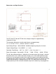
Dimensions and Specifications The PFC-20, PFC-30 and PFC-40 series chargers weigh in at approximately 18 pounds (8.2 kg) The outermost dimensions including foot flanges are approximately 14” L x 10.5” W x 5.75” H (358mm x 264mm x 145mm) Input Voltage Range : 100 to 240VAC 40-80Hz computer grade pure sine wave Output Voltage Range : 12 to 450VDC ( +/- 1 volt ) Operating Temp Range : -20° F to +120° F ( -28.8° C to +48.8° C ) Power Consumption : Up to 9.6kW ~ PFC40 / 7.2kW ~ PFC30 / 4.
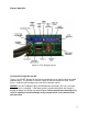
Charger Operation figure 02. PFC Charger Layout Turning the Charger On and Off There is an ON/OFF Breaker to the right of the cooling fan (or coolant fittings on liquid cooled models). This breaker is the main switch to turn the charger on or off. If ever there is a concern while charging first shut off this breaker switch.
User Control Panel The user interface panel is the long blue panel with yellow text near the top of the PFC charger. The main things most users need to be concerned with are the LED indicators, the VOLTS TRIM and the adjustable AMPS knob. Below are explanations of each feature in order from left to right. Refer to figure 02 for specific locations. “VOLTS TRIM” This controls the peak DC voltage ceiling that the charger will allow the batteries to reach before limiting the current.
VOLTS TRIM CALIBRATION: Final tuning is best accomplished when the battery pack is fully charged. The lower the state of charge, the more the user will need to monitor and adjust the unit during the first charge cycle. 1. Turn the amps knob all the way down (full counterclockwise). 2. Make sure the charger is plugged into the battery pack and that there are no open breakers or open fuses in the DC battery circuit. 3.
“REG BUS” This is the 6 pin RJ jack where the BMS communication line plugs into the charger. This port allows the individual battery regulators to communicate with the charger. For more information on the specific reg bus pins refer to the “Reg Bus Wiring” section later in this manual. NOTICE! If your vehicle is equipped with a Battery Management System, ensure that the reg bus data cable is fully plugged into the charger whenever the vehicle is charging.
adjust this knob when the charger is plugged in to a public outlet especially if there is no easy access to the electrical panel for that circuit. Additionally, the user might need to turn down the charger if there are other loads on the branch circuit (example: A stereo and a computer are running on the same 15 amp circuit).
“DIP SWITCHES” The red and white dip switch module is on the upper right end of the charger. This is a bank of 8 switches and they are numbered starting with #1 on the far right. NOTICE! Adjusting these switches can cause the charger to perform in an undesirable manner. Please be sure you understand these switch features before changing them. Dip Switch Guide: 1. Engages timer at peak voltage limit set point. This switch should be ON. 2. Starts timer as soon as the charger is turned on.
Connecting the Charger to the Battery Pack Looking at the front of the charger, you will see that the lower DC output cable has a gray SB-50 Anderson connector on it. This SB-50 is quite common on EV battery chargers and we recommend that you leave this plug on the cord. The SB-50 connector has clearly marked positive and negative sides. Measure the distance from your most positive battery terminal to your PFC charger’s SB-50 connector.
Now you should have a gray SB-50 connector with a positive and negative wire coming out. (See figure 05) Use the appropriate lug or connector for your battery terminal and connect it onto the other end of each cable. Connect the positive cable to the most positive terminal of the battery pack. Connect the negative cable to the most negative terminal of the battery pack.
Ohm’s law states that Volts x Amps = Watts of power and there are a certain number of “Watt Hours” stored in your battery pack and available to power your electric vehicle. Based on the VxA=Watts equation it is easy to see that more volts or amps (or both) equates to more total watts which means more electrical power moving thus faster charging.
PFC-40 Wiring The PFC-40 is shipped with a NEMA 14-50 on the AC input cable. Please leave this attached and make adapter cords if you intend to change what it plugs in to. The 14-50 outlet is very common at RV parks, electric ovens and some public charging stations. To attach the PFC-40’s input cable to a common 110/120V three prong 5-15 or 5-20 plug purchase a 14-50 receptacle and make an adapter exactly as shown in figure 08.
figure 07.
figure 08.
Reg Bus Wiring The Reg Bus Interface: The REG BUS communicates to the charger when any BMS regulators are regulating and also if any regs are too hot. The charger uses this information to determine when to turn down the charge current and when to turn off the charger. The interface contains six wires connected with their respective pins as follows: 1. WHITE : Power supply (+5 volt DC) 2.
of the ambient temperature and how fast the vehicle needs to get back into service. Higher temperatures will make the absorption phase take less time but is more risky to the regulators. When the upper thermal threshold on a regulator has been reached, the reg will pull the hot reg line to +5 volts. This will tell the charger to stop charging until the temperature of the heat sink drops below the thermal limit.
figure 09. Correct RJ Cable Orientation Step 6: Double check that the blue wire is to the right side with the tang down and then take the RJ crimping tool in your right hand. With your left hand push the cable with un-crimped plug into the 6-pin die on the crimping tool. Step 7: While using your left hand to make sure that the RJ cable is firmly held all the way into the connector, squeeze the crimping tool all the way with your right hand to complete the crimp.
figure 10. Side View of Proper RJ Cable For more information visit: www.manzanitamicro.