
Owner`s manual


9
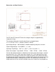
“REG BUS”
This is the 6 pin RJ jack where the BMS communication line plugs into the charger.
This port allows the individual battery regulators to communicate with the charger. For
more information on the specific reg bus pins refer to the “Reg Bus Wiring” section later
in this manual.
NOTICE! If your vehicle is equipped with a Battery Management System, ensure that
the reg bus data cable is fully plugged into the charger whenever the vehicle is
charging. The communication data cables are hooked to the regulators in a daisy chain
fashion. Make sure that each of the smaller data cables are all plugged in where they
should be before charging. If there is an unplugged portion of the reg bus, the
charger cannot communicate with the regs and this could lead to a potentially
damaging situation if there is an un-matched battery cell in the pack! The RJ
connectors are similar to phone cord connectors and they are designed to snap into
place and stay connected. If a cable is disconnected insure that it is fully reconnected.
An audible *click* should be heard when the RJ plug is fully inserted and it should not
be able to be pulled out without first pinching the small plastic tab underneath the plug.
For more information on reg bus cables refer to the “Reg Bus Wiring” section later in
this manual.
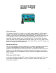
“POWER” - Green LED
The bright green POWER LED indicates when the charger is on. Input power is being
supplied to the unit and the main breaker is in the ON position.
“WARN” - Red LED
The red WARN LED should blink briefly when the charger is first powered up and then
remain off for the duration of the charge. If this indicator stays on, turn down the AMPS
knob immediately, turn off the charger’s breaker switch and consult Manzanita Micro or
a qualified service technician. This LED could indicate an over voltage or over
temperature condition. It could also be indicative of an open circuit condition in the
pack. Turn down the AMPS knob and check to make sure there is no open circuit
condition in the battery pack. Check the gray SB-50 Anderson connector to insure that it
is tightly connected and look for other disconnected battery cables. If the charger will
not work and the circuit is complete, contact Manzanita Micro.
NOTICE! DO NOT let the charger try to put current into the battery pack if there is an
open circuit condition in the circuit. Never unplug the gray SB-50 Anderson connectors
(DC line) from your charger while it is charging! If the battery pack is disconnected
while the charger is putting out power the charger can be damaged. Failure to heed
these warnings may result in significant internal damage to the charger which is
not covered under your warranty!
“AMPS” Knob
The AMPS knob allows the user to adjust how much current the charger will move. If
the vehicle is always plugged in to the same circuit this shouldn’t need any adjusting but
if the user were to have it set at 35 amps and then plug into a 15 amp 110V outlet it will
quickly open a circuit breaker or fuse on the AC line. The vehicle operator may wish to