
Manual


78 EZwarePlus Programming Manual
1010-1015, Rev. 03
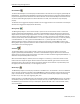
History Data Display
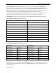
The History Data Display Object is used to display historical data collected by the Data Sample Object in a table
format. Up to 16 channels of data can be displayed from consecutive addresses, and can be any mix of data
types (e.g., 16-bit unsigned, 16-bit signed, 32-bit float, etc.).
Note: The History files section in the Data Sampling Object must have a box checked (e.g., Save to HMI
memory) and a Folder name defined in order for the data files to be stored and displayed in the History Data
Display.
The History Control register is used to select the historical data file to display. When the value in the History
Control
register is 0, the data for today is displayed in the table. When the value is 1, the data from yesterday is
displayed, etc.
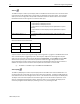
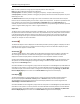
Data Block Display
The Data Block Display Object is used to draw line graphs of the data contained in consecutive registers (up to
1024 consecutive registers). In addition, up to 12 individual sets of data can be displayed in the Data Block
Display. The line graphs can display data in any supported format, but the data in each graph must be of the
same format.
The Y-axis scaling is configured on the General tab with the Minimum and Maximum Limit fields (this defines
the bottom and the top of the Data Block Display and should contain the range of data values). The X-axis
scaling is configured on the Display Area tab in the Data Samples field (this defines the number of data
samples to plot on a single screen).
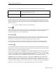
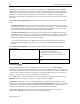
The Control address specifies the address to use to control the selected channel (data set). Each channel has
its own Control Word address. The following values can be written to the Control address to control the plot:
Trigger Value
Control Function
1
Draws the plot for the selected channel, leaves existing data.
Can display up to 32 plots for 1 channel, 16 plots for 2 channels, 8 plots for 4 channels, etc.
2
Clears the plot for the selected channel.
3
Clears the plot for the selected channel, then redraws the plot with the current data.
The HMI will write a 0 to the Control Word address after the operation is complete.
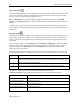
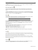
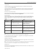
If Offset to start address is unchecked, the following addresses are used by the Data Block Display:
Control Word address
Draws/clears the plot
Control Word address + 1
Defines number of data points to plot (n = up to 1024)
Data storage start address
First data point to plot
Data storage start address + 1
Second data point to plot
Data storage start address + n +
1
Last data point to plot
n = number of data samples