HMI5000L Series Installation Guide Introduction Thank you for purchasing a Maple Systems HMI5000L Series graphic industrial operator interface terminal. The HMI5000L Series touchscreens are configured using the EZwarePlus software (purchased separately) and include the following models: HMI5043L, HMI5070L, HMI5070NL, HMI5100L, HMI5121XL, and HMI5150XL. This booklet describes the steps necessary for installing the HMI5000L Series touchscreens.
HMI5000L Installation Guide Static Awareness Do NOT remove the rear cover of your HMI5000L Series product – doing so will void your warranty. When the rear cover is removed the circuitry inside is exposed to possible damage by electrostatic discharge during handling. Minimize the possibility of electrostatic discharge by: Discharging personal static by grounding yourself prior to handling the HMI. Handling the HMI at a static-free grounded workstation.
HMI5000L Installation Guide 3 Warranty Maple Systems warrants each product to be free from electrical and mechanical defects in materials and workmanship for a period of one (1) year for the LCD display and backlight and two (2) years for all other parts and labor from the date of shipment.
HMI5000L Installation Guide Installation of HMIs CE Compliance The HMI5000L Series Graphic HMIs have been tested to conform to European CE requirements, which meet or exceed the noise emissions and immunity requirements as set forth in the EN55022 (Emissions) and EN55024 (Immunity) standards. The products are designed to withstand electrical noise in harsh industrial environments. They also conform to requirements that limit electrical emissions.
HMI5000L Installation Guide 5 vibration or shocks. Do not install the HMI in enclosures with rapid temperature variations or high humidity. Either case will cause condensation of water inside the device and eventual damage to the HMI. Safety Precautions Please observe the following precautions when installing the HMI. Failure to comply with these restrictions could result in loss of life, serious personal injury, or equipment damage.
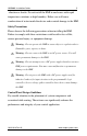
HMI5000L Installation Guide Figure 1: Typical Panel Layout 1. Also HMI5121XL and HMI5150XL 2. Also HMI5043L and HMI5070NL Control Panel Grounding The control panel must be connected to a good, high-integrity earth ground both for safety considerations and shielding purposes. Maple Systems cannot overemphasize the importance of good grounding. If you fail to use good grounding procedures during installation, sporadic malfunction of the HMI may occur.
HMI5000L Installation Guide 7 strip. This will ensure that no ground current from one device influences the operation of the other devices. Connect the HMI chassis ground terminal to the control panel door using a heavy-gauge short braided cable or ground wire to minimize resistance. Connect the power cable’s shield wire to the HMI’s chassis ground terminal. Connect the control panel to earth ground using a copper grounding rod close to the HMI and control panel.
HMI5000L Installation Guide NOTE: If the control panel is made of a non-conductive material, it is essential that you connect the chassis ground terminal of the HMI to a clean earth ground point located close to the panel. NOTE: The power and frame ground wiring on the HMI5043L, HMI5070NL and HMI5070L is different from the HMI5100L, HMI5121XL, and HMI5150XL. Please refer to Figures 2a and 2b.
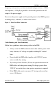
HMI5000L Installation Guide 9 Figure 2b: Chassis Ground Connection – HMI5100L, 5121XL, 5150XL Metal area on panel free of paint Stud or screw Frame ground Green (FG) Control Panel (connected to earth ground) Red (+) Power Supply Selection Black (--) The power supply used to power the HMI should provide an output of +24 VDC ±20% measured at the HMI power terminal block. A 24VDC regulated power supply dedicated to the HMI is recommended.
HMI5000L Installation Guide frequency noise present, we also recommend using a resistor (~1 MΩ) and capacitor (~4700 pF) in parallel to clean earth ground on the DC output of the power supply. Do not use the power supply used to provide power to the HMI to power switching relays, solenoids, or other active devices.
HMI5000L Installation Guide 11 Run AC power wires in a separate grounded conduit to reduce electrical noise interference. Keep the cable lengths for the HMI as short as possible. Do not coil excess cable and place it next to AC powered equipment. Cover any equipment used in the enclosure that operates at high frequency or high current levels with a grounded metal shield.
HMI5000L Installation Guide Figure 4: HMI Power Wiring To connect the HMI to power: 1. Connect the power cable to the HMI. a. Strip the power cable shield to expose 2” of the black and red wires. b. Strip about ¼” of insulation from the black and red wires. c. Connect the red wire to the 24V DC positive (+) input of the HMI power terminal block. d. Connect the black wire to the 24V DC negative (–) input of the HMI power terminal block. e.
HMI5000L Installation Guide 13 3. Install the power supply wires as follows (with colors shown for Maple Systems cable P/N 6030-0009): Color Red Black Shield Power Supply +Output/+24V DC –Output/+24V DC return Case ground HMI +24 V GND FG or NOTE: The power connector on the HMI5000L Series uses a 3-position terminal block with screw-down clamps. Lugs are not required. Panel Preparation A metal panel or mounting surface with a minimum thickness of 15 gauge (0.059 in/3.
HMI5000L Installation Guide prevent the gasket from sealing properly. If the panel or mounting surface is not uniform, thick, flat, stiff, or smooth enough, then a sealant such as silicone may be required. NOTE: Clean and deburr the panel cutout before the HMI is installed. Warning: The HMI requires a stiff, flat, smooth mounting surface free of blemishes to seal properly to NEMA 4. All supplied mounting clamps must be used and the panel cannot flex more than 0.010”.
HMI5000L Installation Guide 15 2. Set the HMI in the panel cutout and hold it in place until all clamps are in position. 3. Tighten the screw clamps in an even pattern until all are uniformly snug. Caution: Do not over-tighten the screws beyond snugness or you may damage the housing or warp the overlay. REINSTALLATION: If, at any time, you are required to reinstall an HMI into a panel, be aware that the gasket will take a ‘set’ to the panel and may no longer provide an adequate NEMA 4 seal.
HMI5000L Installation Guide Maintenance Figure 6: DIP switch positions (power must be cycled on the HMI to enable the DIP switch mode). (Except HMI5043L, HMI5121XL, HMI5150XL) SW1 SW2 SW3 SW4 Mode ON OFF OFF OFF Calibration mode OFF ON OFF OFF Hide System Toolbar OFF OFF ON OFF Force into Boot Loader mode OFF OFF OFF ON Reserved OFF OFF OFF OFF Normal operation Touchscreen Calibration mode: This mode allows you to recalibrate the touchscreen.
HMI5000L Installation Guide 17 Serial Port Connections The diagrams below indicate the proper pin connections for the serial ports of the HMI5000L Series. Figure 7a: Serial Port Pinouts HMI5043L 1010-1018 Rev 01 www.maplesystems.
HMI5000L Installation Guide Figure 7b: Serial Port Pinouts HMI5100L, HMI5070L, HMI5070NL HMI5100L HMI5070L, HMI5070NL* * No Ethernet connection on HMI5070NL 1010-1018 Rev 01 www.maplesystems.
HMI5000L Installation Guide 19 Figure 7c: Serial Port Pinouts HMI5121XL, HMI5150XL Note: COM1 [RS-485 2W] and COM3 [RS-485 2W] support the Siemens MPI 187.5K multi-point interface. However, only one COM port can be used with the Siemens MPI interface at a time. 1010-1018 Rev 01 www.maplesystems.
Maple Systems Inc. th 808 134 Street SW, Suite 120 Everett, WA 98204-7333 Phone: (425) 745-3229 Email: maple@maplesystems.com Web: www.maplesystems.com © 2014 Maple Systems Inc. All rights reserved.