
Owner manual

MAPware-7000 Ladder Logic Guide 178
1010-1041 rev. 00
Instruction 112- Direct I/O
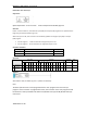
Expression:
Space Requirement: 1 line x 3 column Location Requirement: Middle, Right rail
Function:
Under normal conditions, the external input (XW) and output (YW) registers are updated at the
beginning of each PLC ladder logic scan.
When the input is ON, this instruction immediately updates the target input (XW) or output
(YW) register.
For XW register ... reads the data from targeted input circuit
For YW register ... writes the data into targeted output circuit.
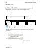
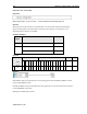
Execution Condition:
Set Input
Operation
Output
OFF
No execution
OFF
ON
Execution
ON
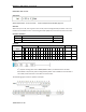
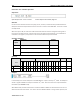
Operand:
Coil or Bit
Register
Constant
Index
Name
X
Y
B
S
T.
C.
M
X
W
Y
W
B
W
S
W
T
C
D
I
J
K
M
W
N
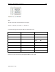
Register Size
1
A
Start of
Registers
√
√
Example:
When B010 is ON, the XW00 register is updated immediately.
Note:
The Direct I/O instruction can be programmed in the main program and in the interrupt
program. If this instruction is programmed in both, the instruction in the main program should
be executed in interrupt disable state. Refer to EI (Enable interrupt) and DI (Disable Interrupt)
instructions.