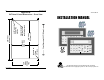
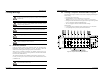
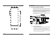
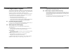
24 OIT3165A/4165A 1010-0102, REV 05 Appendix D OIT Panel Cutout Dimensions – Front View 3.50" +/-0.01 88.9mm +/-0.3 1010-0102, REV 05 Check Dimension 4.00" [101.6 mm] R0.08" max. 2.0mm 4 Places 5.10" +/-0.03 129.5mm +/-0.8 Connect mounting stud(s) to control panel earth ground 3.70" +/-0.03 94mm +/-0.8 5.60" +/-0.01 142.2mm +/-0.3 0.172" +/-0.01 Dia., 4.4mm +/-0.
OIT3165A/4165A COPYRIGHT NOTICE This manual is a publication of Maple Systems, Inc., and is provided for use by its customers only. The contents of the manual are copyrighted by Maple Systems, Inc.; reproduction in whole or in part, for use other than in support of Maple Systems equipment, is prohibited without the specific written permission of Maple Systems.
22 OIT3165A/4165A INSTALLATION MANUAL 3 Appendix B Agency Ratings UL Class I, Division 2 Groups A,B,C,D hazardous locations.
OIT3165A/4165A INSTALLATION MANUAL Introduction Thank you for purchasing a Maple Systems OIT3165 or OIT4165. You have selected a rugged, reliable, and powerful operator interface for your application. This booklet describes the steps necessary to ensure trouble-free OIT system operation. Please read this booklet carefully!! Static Awareness It is best NOT to remove the rear cover on the OIT.
20 OIT3165A/4165A 5.4. Installing a Slide-In Legend To replace the factory installed legend with your own: 1. Ensure all paints, inks and fixative are thoroughly dry and will not transfer. 2. Place the unit face down on a clean protective surface. 3. Locate the legend access slot along the right side of the cover. 4. Remove the tape from the existing legend and then pull the legend out. 5. Slide in the new legend (refer to Figure 11).
OIT3165A/4165A 1. Safety Warnings WARNING Hazardous location environment. This unit is suitable for use in Class I, Division 2 groups A, B, C and D or Non-Hazardous locations only. WARNING All input and output (I/O) wiring must be in accordance with Class I, Division 2 wiring methods and in accordance with the authority having jurisdiction. WARNING Explosion hazard. Do not disconnect equipment unless power has been switched off or the area is known to be non-hazardous. INSTALLATION MANUAL 19 5.3.
18 OIT3165A/4165A INSTALLATION MANUAL 7 2. Control Panel Design Guidelines The following guidelines are intended to illustrate proper installation of the OIT to help minimize electrical noise, which may hamper normal operation. It is the responsibility of the customer to ensure that all wiring and other components used in the control system meet Class I, Division 2 requirements.
OIT3165A/4165A INSTALLATION MANUAL 17 • Input and output (I/O) wiring must be in accordance with Class I, Division 2 wiring methods and in accordance with the authority having jurisdiction. • Always route the OIT communication cable and power cable away from any AC voltage or PLC/host control wires. • Never bundle the OIT cables together with 120 VAC power wires or with relay wiring. • Try to keep at least 8 inches (20 cm) of separation between the OIT cables and other power wiring.
16 OIT3165A/4165A 5. Custom Keypad Slide-In Legends The OIT3165 and OIT4165 have a graphic overlay covering the keypad. This overlay contains a clear window that allows you to insert your own legend to customize the keypad’s text, colors, and graphics. This legend can be inexpensively made and is environmentally sealed when installed. The slide-in legend can be made on any non-glossy stock between 0.004 inches (0.1 mm) and 0.008 inches (0.
OIT3165A/4165A 3. OIT Installation It is necessary to follow all installation procedures described in this chapter for electrical noise immunity and CE compliance. Your Maple Systems OIT is designed to connect easily to your PLC. External connectors provide quick connection for power and communications wiring. • There is one serial port with an RJ-45 shielded jack. This port is used to connect to the PLC and to configure the OIT.
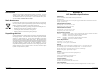
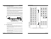
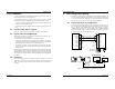
14 OIT3165A/4165A 3. Route the communication cable to the PLC/host. Refer to the “OIT Cable Routing” section for more information. 4. Connect the other end of the cable to the PLC/host and tighten the cable screws. PIN# 1 2 3 4 5 6 7 8 INSTALLATION MANUAL 11 3.4. Mount OIT to Panel FUNCTION TXD+ TXDCTS RETURN TXD RXD RXDRXD+ Figure 6 Port 1 Pin Outs 5. Connect the green shield wire from the cable to earth ground (chassis ground) on the PLC.
OIT3165A/4165A 3.5. Connect OIT to Power INSTALLATION MANUAL 2. WARNING Use only with Class 2 power source limited to 30 VDC open circuit and 8A short circuit. The power cable for the OIT should be 18AWG 2-conductor wire with a shield wire and protective shield foil. Maple Systems sells cable P/N 6030-0009 by the foot for user-built power cables.