Table of Contents INTRODUCTION: Welcome . . . . . . . . . . . . . . . About Your Documentation . . . . . . . . . . . . . Conventions . . . . . . . . . . . . . . . . . . . . . OIT Models Supported . . . . . . . . . . . . . . . . . Operational Overview . . . . . . . . . . . . . . . . . i i i ii ii CHAPTER 1: Getting Started. . . . . . . . . . . . . . . What You Will Need . . . . . . . . . . . . . . . . . . Installing STEPware-100 . . . . . . . . . . . . . . . STEPware-100 Tutorial. . . . . . . . . . . . . .
Introduction i INTRODUCTION Welcome Welcome to Maple Systems’ STEP1 Standard Terminal Emulation Protocol, a powerful terminal emulation protocol for use with Maple Systems’ Operator Interface Terminals (OITs) in industrial applications.
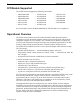
ii STEP1 Protocol Operation Manual OIT Models Supported The STEP1 Protocol supports the following OIT models: • MAP320D-240B • OIT3185-A00 • OIT4175-A00 • MAP340D-240F • OIT3200-B00 • OIT4185-A00 • MAP460D-240B • OIT3250-B00 • OIT4400-B00 • OIT3160-A00 • OIT3600-B00 • OIT4450-B00 • OIT3165-A00 • OIT4160-A00 • OIT5400-B00 • OIT3175-A00 • OIT4165-A00 Previous models, such as the MAP320B-240B or OIT3200-A00, are not supported.
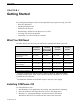
Getting Started 1 CHAPTER 1 Getting Started The Getting Started chapter walks you through all the steps required to setup your OIT: • What You Will Need • Installing STEPware-100 • STEPware-100 Tutorial • Downloading a STEPware-100 Project to Your OIT • Verifying Your OIT is Operational • Connecting Your OIT to the Host Controller What You Will Need The table, below, lists the items you will need to configure and operate your OIT.
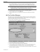
2 STEP1 Protocol Operation Manual 4. Type a:\setup (substitute b for a if your 3.5-inch drive is configured as the b drive). 5. Choose the OK button. 6. Follow the instructions on your screen. NOTE: When installation of STEPware-100 is complete, your PC must be restarted before STEPware-100 will operate correctly. STEPware-100 Tutorial Create a Basic STEPware-100 Project This step walks you through the creation of a basic STEPware-100 project named SAMPLE.SWR.
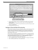
Getting Started 3 5. The Configuration Editor is used to specify the OIT’s operating parameters. Refer to Chapter 2: OIT Configuration for more information. When finished setting the OIT’s operating parameters, choose the Done button to return to the STEPware-100 main screen. NOTE: The sample communication session in the “Verifying Your OIT is Operational” section later in this chapter is written to communicate to your PC.
4 STEP1 Protocol Operation Manual The special characters displayed here are inserted into the message when you choose the Done button. 6. Choose the Done button to return to the STEPware-100 main screen. The special character displayed in the text box next to the Add To List button displays in the Message Editor. 7. In the Message Editor, following the special character you just inserted, type a space and then type characters. 8. From the File menu, choose Save.
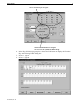
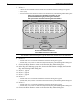
Getting Started 5 Select a function key to configure. Choose the Edit buttons to configure the "on" and "off" predefined ASCII strings. 4. In the Key ON Message group box, choose the Edit button to display the Function Key ASCII String Editor dialog box. 5. In Pos. 1, type o. 6. In Pos. 2, type n. 1010-0096, Rev.
6 STEP1 Protocol Operation Manual 7. In Pos. 3: • choose the Non-Printable button and the Non-Printable Characters dialog box appears • select {CR} • then choose the Done button to return to the Function Key ASCII String Editor dialog box. Place one of these non-printable characters in your predefined ASCII string by selecting the character with your mouse and then choosing the Done button. Choose the Extended button to select ASCII characters 128 to 255.
Getting Started 7 Configure a Momentary Function Key Momentary function keys can be configured to repeat the predefined ASCII string while the function key is pressed. The time interval between transmissions of the ASCII string can be set between 10 msec and 30 sec. In addition a maximum limit can be set, 1 to 1000, after which the function key is no longer recognized until it is released and pressed again.
8 STEP1 Protocol Operation Manual 6. In Pos. 7: • double click Pos. 7 and the Non-Printable Characters dialog box appears • double-click {CR} to select CR and return to the Function Key ASCII String Editor dialog box. 7. In Pos. 8: • double click Pos. 8 and the Non-Printable Characters dialog box appears • double-click {LF} to select LF and return to the Function Key ASCII String Editor dialog box. 8. Choose the Done button to return to the Function Key Editor dialog box. 9.
Getting Started 9 Downloading a STEPware-100 Project to Your OIT Connect OIT to PC and Power Supply PC Printer OIT3250 OIT4450 OIT5400 OIT (Rear of OIT) Com2 Com1 Port 2 Port 1 Power OIT Power Supply GND+ - Maple Systems OIT to PC cable (If mouse is using Com 1, use Com2) 7431-0049 7431-0050A PC Printer Com2 Com1 OIT3200 OIT4400 OIT (Rear of OIT) Port 1 Power OIT Power Supply GND+ - Maple Systems OIT to PC cable (If mouse is using Com 1, use Com2) 7431-0049 7431-0050A PC Printer Com2 Co
10 STEP1 Protocol Operation Manual Place OIT in Download/Upload Mode New OIT NOTE: If using an OIT3160 or OIT4160, refer to the Existing OIT section below. NOTE: If using an OIT3165/4165, OIT3175/4175 or OIT3185/4185, refer to Appendix D for the setup keyboard layout.
Getting Started 11 3. Next, press the [ENTER] key to display the following message: OIT Model OIT3100 and OIT4100 Series All other models Message Password? Enter Setup Password? 4. Type the setup password and then press the [ENTER] key on the OIT. If there is no setup pasword, just press the [ENTER] key. The following message appears: OIT Model OIT3100 and OIT4100 Series All other models Message Down/Upload Mode? Y Download/Upload computer? YES 5.
12 STEP1 Protocol Operation Manual To download a STEPware-100 project to the OIT: 1. Start STEPware-100 and open your project. NOTE: The OIT must be in Download/Upload mode to accept a project from STEPware-100. 2. From the Transfer menu, choose Send to OIT. The STEPware 100 - Send To OIT dialog box appears. 3. Choose the Options button. The Communication Options dialog box appears. 4.
Getting Started 13 Verifying Your OIT is Operational Connect OIT to PC and Power Supply PC Printer OIT3250B OIT4450B OIT5400B OIT (Rear of OIT) Com2 Com1 Port 2 Port 1 Power OIT Power Supply GND+ - Maple Systems OIT to PC cable (If mouse is using Com 1, use Com2) 7431-0049 7431-0050A PC Printer MAP320D MAP340D OIT3200B OIT4400B OIT (Rear of OIT) Com2 Com1 Port 1 Power OIT Power Supply GND+ - Maple Systems OIT to PC cable (If mouse is using Com 1, use Com2) 7431-0049 7431-0050A PC Printer
14 STEP1 Protocol Operation Manual Setup PC’s Terminal Emulation Program 1. Start your terminal emulation program. 2. Verify settings: • • • • Baud Rate = 9600 Data Bits = 8 Stop Bits = 1 Parity = None • Handshaking (Flow control) = None • Terminal Emulation = VT-100 or equivalent • Local Echo = Enabled Sample Communications Session Before executing this sample communications session, you should have completed: • STEPware-100 Tutorial (create SAMPLE.
Getting Started 15 Connecting Your OIT to the Host Controller The information in this section is supplemental to the information in your OIT Installation Manual. Please read this section and your OIT Installation Manual before installing your OIT. RS-232 (Interactive & Block modes) Interactive and Block modes support the 3-wire RS-232 configuration with TXD, RXD, and signal common. The cable requires an overall shield to protect against electrical noise.
16 STEP1 Protocol Operation Manual Host Controller TXD+ TXDRXD+ RXDsignal ground 5-Wire RS-422/485 OIT Port 1 OIT Terminal Block (OIT3100 and (MAP460D, OIT3600) OIT4100 Series) Pin 4 — RXD+ Pin 8 — RXD+ Pin 5 — RXDPin 7 — RXDPin 6 — TXD+ Pin 1 — TXD+ Pin 7 — TXDPin 2 — TXDPin 8 — return Pin 4 — return OIT Port 1 (all other models) Pin 4 — RXD+ Pin 1 — RXDPin 9 — TXD+ Pin 6 — TXDPin 5 — return RS-422/485 (Network mode) Network mode supports the 3-wire and 5-wire RS-422/485 configurations.
Getting Started 17 OIT Jumper All of the OITs, except the OIT3100 and OIT4100 Series, have a jumper that must be moved when connecting the OIT to a network. Refer to the Set Jumper for Specific Protocol section in the OIT Installation Manual.
18 STEP1 Protocol Operation Manual 5-Wire RS-422/485 (Network mode) Power Supply +24V OIT +24V TB1 1 GND From or To Host or OIT Shield 2 * COM 3 RXD+ 4 CHASSIS GND TXD+ RXD- 5 TXD- TXD+ 6 RXD+ TXD- 7 8 RXD- * RTN OIT DE9P From or To Host or OIT Shield RXD+ 4 CHASSIS GND TXD+ RXD- 1 TXD- TXD+ 9 RXD+ TXD- 6 RXD- Return 5 SIG GND SIG GND SIG GND SIG GND * RTN and COM are internally connected in OIT.
Getting Started 19 3-Wire RS-422/485 (Network mode) Power Supply +24V OIT TB1 1 GND 2 From or To Host or OIT * COM 3 RXD+ 4 CHASSIS GND RXD- 5 TXD+ 6 TXD* RTN 7 8 +24V Shield RXD+/TXD+ RXD-/TXDSIG GND OIT From or To Host or OIT DE9P Shield RXD+ 4 TXD+ 9 RXD- 1 TXD- 6 CHASSIS GND RXD+/TXD+ RXD-/TXDSIG GND Return 5 SIG GND SIG GND * RTN and COM are internally connected in OIT.
20 STEP1 Protocol Operation Manual TERMINATOR TERMINATOR HOST OIT3600 Vcc MAP460D HOST TERMINATION END TERMINATION FROM HOST + Tx+ Tx- Rx+ RxSIGNAL GND OIT3160 FROM HOST - 470 Ohm to 10 KOhm 120 Ohm to 240 Ohm TO HOST + 120 Ohm to 240 Ohm 470 Ohm to 10 KOhm TO HOST SIGNAL GND SHIELD CHASSIS GND DO NOT CONNECT EARTH GROUND Network Grounding To communicate properly, serious attention must be paid to the grounding scheme of the devices connected to the com-link.
OIT Configuration 21 CHAPTER 2 OIT Configuration Your OIT must be configured using the STEPware-100 configuration software before it can communicate with your host controller. Refer to Chapter 1: Getting Started for instructions on creating and downloading a STEPware-100 project. After your OIT is configured, some of the OIT’s operating parameters can be changed from the OIT’s keyboard when the OIT is in Configuration mode.
22 STEP1 Protocol Operation Manual 2. At Parameters?, press the OIT’s TOGGLE key to alternate between MODIFY and VIEW, then press the OIT’s ENTER key to accept and continue. Option MODIFY VIEW Description Allows you to enter Download/Upload mode or modify the OIT’s current operating parameters. Displays the OIT’s current operating parameters.
OIT Configuration 23 5. The following Level 1 menus appear in order. If you select YES at a Level 1 menu, the corresponding Level 2 menus appear. If you select NO at a Level 1 menu, the next Level 1 menu appears. At any menu, press the OIT’s TOGGLE key to alternate between the options.
24 STEP1 Protocol Operation Manual Operating Parameters The STEP1 protocol has many operating parameters which determine how the OIT communicates to the host controller. These operating parameters can be configured using the STEPware-100 configuration software or the OIT’s Configuration mode, or by sending Control Commands from the host controller. Each operating parameter is described in detail below.
OIT Configuration 25 Parity Setting This parameter determines the parity that the OIT uses to communicate to the host controller. Options are Even, Odd, None, Mark, Space. When the OIT is in Configuration mode, no parity is used to communicate to STEPware-100 regardless of how this setting has been configured. To modify this parameter using STEPware-100: 1. Open the Configuration Editor. 2.
26 STEP1 Protocol Operation Manual To modify this parameter in Configuration mode: 1. At Stop Bits:, use the OIT’s TOGGLE key to select the desired number of stop bits. Refer to the Configuration Mode section in this chapter for more information. To modify this parameter from the host controller: 1. Use the Set Communications Parameters control command. Refer to Appendix A: Control Commands for more information.
OIT Configuration 27 Hardware Handshaking Hardware handshaking, which uses the CTS/RTS format, is available only in Interactive and Block modes. The following rules apply: 1. OITs with two serial ports must not have a programming cable connected to the second port. 2. OITs with serial printer output capability cannot use the serial printer. 3. When the host controller deasserts the CTS line, the OIT halts transmission of any data to the host controller until the CTS line is reasserted.
28 STEP1 Protocol Operation Manual In all three modes, the line terminator is sent to the host controller when the OIT responds to a control command and when the OIT’s ENTER key is pressed. In Interactive mode, if local echo is enabled when the OIT’s ENTER key is pressed, the line terminator is also sent to the OIT’s display. In Block or Network mode, if block echo is enabled when the OIT’s ENTER key is pressed, the line terminator is also sent to the OIT’s display.
OIT Configuration 29 Local Echo Setting This parameter determines whether local echo is used when the OIT is operating in Interactive mode. If enabled, each character sent to the host controller from an OIT keypress is also sent to the OIT’s display. To modify this parameter using STEPware-100: 1. Open the Configuration Editor. 2. In the OIT Operational Settings group box, select the Local Echo Enabled check box. To modify this parameter in Configuration mode: 1.
30 STEP1 Protocol Operation Manual To modify this parameter in Configuration mode: 1. At Turn Delay:, use the OIT’s TOGGLE key to select the desired turnaround delay. Refer to the Configuration Mode section in this chapter for more information. To modify this parameter from the host controller: 1. Use the Set Turn-Around Delay control command. Refer to Appendix A: Control Commands for more information.
OIT Configuration 31 Network Address Setting This parameter determines the network address used by the host controller to communicate with this OIT when in Network mode. Options are 1 to 255. To modify this parameter using STEPware-100: 1. Open the Configuration Editor. 2. In the OIT Operational Settings group box, enter the desired network address in the Network Addr. text box. To modify this parameter in Configuration mode: 1.
32 STEP1 Protocol Operation Manual To modify this parameter from the host controller: 1. Use the Display and Cursor Format Control control command. Refer to Appendix A: Control Commands for more information. Wrap Around Setting This parameter determines whether the OIT will use ‘word wrapping’ when displaying characters on the OIT screen. If disabled, any characters received from the host or from the keyboard of the OIT are displayed on the OIT screen at the location of the cursor.
OIT Configuration 33 Key Click Setting This parameter determines whether an audible key click occurs whenever a key is pressed on the OIT’s keyboard. To modify this parameter using STEPware-100: 1. Open the Configuration Editor. 2. In the OIT Operational Settings group box, select the Key Click Enabled check box. To modify this parameter in Configuration mode: 1. At KeyClick:, use the OIT’s TOGGLE key to enable or disable the local keyboard.
34 STEP1 Protocol Operation Manual To modify this parameter using STEPware-100: 1. Open the Configuration Editor. 2. In the OIT Operational Settings group box, choose the Editor button to open the Password Editor dialog box. 3. In the Setup text box, enter a five-digit numeric password. 4. Choose the Done button. To modify this parameter in Configuration mode: 1. At Setup Password, use the OIT’s numeric keys to enter a five-digit numeric password.
Operating Modes 35 CHAPTER 3 Operating Modes Your OIT can be programmed to operate in one of three operating modes: Interactive, Block, or Network. These modes affect how the OIT sends data to and receives data from the host controller. This chapter explains the differences between the three operating modes. Refer to Chapter 2: OIT Configuration for information on how to change the operating mode. Interactive Mode In Interactive mode, the OIT immediately sends data to the host controller.
36 STEP1 Protocol Operation Manual OIT Key Enter Function Keys & Screen Dependent Function Keys Data Sent to Host Local Echo Mode Operation If the line terminator is ETX, this key has no affect. If the line terminator is CR, the cursor moves to the first column of the current line. If the line Line Terminator terminator is LF or CR/LF, the cursor moves to the (ETX, CR, LF, or CR/LF) first column of the next line.
Operating Modes 37 OIT Key Delete Enter F1 to F16 and SDF1 to SDF5 Operation Deletes the last character entered into the Keyboard Input Buffer, deletes the character to the left of the cursor and moves the cursor one position left. If the cursor is at the original data entry starting position, this key has no affect. If the cursor is on the last position of a line and a character is displayed there, the character is deleted and the cursor remains on the last position of the line.
38 STEP1 Protocol Operation Manual When using Network mode, always follow these rules: 1. Every OIT on the network must be assigned a unique network address. 2. Every OIT on the network must be programmed to use the same line terminator. 3. Always have the host controller send a line terminator immediately before sending an OIT network address.
Operating Modes 39 Sample Network Session Below is a sample session showing a host controller communicating with three OITs on a multidrop network. The OITs have network addresses of 1, 30, and 100. The line terminator is set to ETX. NOTE: Spaces are shown for clarity only and should not be used.
40 STEP1 Protocol Operation Manual This page intentionally left blank. 1010-0096, Rev.
Using the OIT's Display 41 CHAPTER 4 Using the OIT’s Display The OIT displays data input from the OIT’s keypad, data sent from the host controller, and data stored in predefined messages. When a printable ASCII character is sent to the OIT’s display, it is displayed at the OIT cursor’s current location (unless the host controller is writing to a display variable). The cursor is then advanced one column to the right on the current display line.
42 STEP1 Protocol Operation Manual • in Interactive mode, additional characters overwrite the character in the last column, unless the word-wrap feature is enabled. If word-wrap is enabled, the cursor moves to the next line of the display. • in Block or Network mode, the OIT sounds an error beep and stops accepting keypad input. In Network mode, once the OIT’s ENTER key is pressed, the OIT no longer accepts keypad input until the host controller either polls or clears the OIT’s Keyboard Input Buffer.
Using the OIT's Display OIT Key Function Keys & Screen Dependent Function Keys 43 Interactive Mode Displays the predefined ASCII string or, if the Display Message feature is enabled, the predefined message. If the predefined ASCII string contains control characters, they are displayed as $.
44 STEP1 Protocol Operation Manual on creating, writing to, and deleting display variables. Refer to Appendix A: Control Commands and Appendix B: Control Codes for more information. To create a display variable: 1. Have the host controller position the OIT’s cursor in the location where you want to start the display variable. 2. Have the host controller send the Create Display Variable control command (ESC w length terminator).
Using the OIT's Display 45 Notice that part of Message #25 has been truncated with the last character of the message located in the last position of Line #2. Refer to Appendix A: Control Commands for more information on the Display Message control command. Optional Settings for Predefined Messages Each predefined message can be configured with optional controls which the OIT will perform either before or after a message is displayed on the OIT screen.
46 STEP1 Protocol Operation Manual This page intentionally left blank. 1010-0096, Rev.
Using the OIT's Function Keys 47 CHAPTER 5 Using the OIT’s Function Keys The OIT’s function keys provide the ability to create a predefined string of characters called ‘ASCII Strings’ that can be sent to the host controller whenever the function key is used. Each function key can also be programmed to display the ASCII Strings on the OIT screen or to display some predefined message.
48 STEP1 Protocol Operation Manual • ENTER key - this action allows the function key to behave as an ENTER key, enabling the OIT operator to send a line terminator to the host and perform other actions when the OIT is in Block or Network mode. This action is only available on OIT models that do not have a predefined ENTER key, (such as the OIT3100 and OIT4100 Series). The ENTER key will behave differently according to the operating mode used. Refer to Chapter 3: Operating Modes for more information.
Using the OIT's Function Keys 49 Each state of the function key can be configured to send a predefined message to the OIT screen. This allows a different message to be displayed depending upon the action of the key, (i.e. momentary, push on/off, etc.). For each function key, the OIT programmer has the option of selecting Message#1-30 for the ON state (Key ON Message) and Message#31-60 for the OFF state (Key OFF Message).
50 STEP1 Protocol Operation Manual 2. In the Assignment group box, select the appropriate option button. 3. In the Action drop down list box, select Push On/Off. 4. In the Key ON Message group box, choose the Edit button to display the Function Key ASCII String Editor dialog box. 5. Enter your ASCII string in the Char. row of the table. • To enter printable ASCII characters, just press the appropriate key on the PC’s keyboard. • To enter non-printable ASCII characters, either double click in the Char.
Using the OIT's Function Keys 51 6. Choose the Done button to return to the Function Key Editor dialog box. 7. If you want to program a Key OFF Message, repeat steps 4 through 6 using the Edit button in the Key OFF Message group box. 8. If you want to use the Repeat feature, in the Repeat group box, select the Enable check box and then set the Interval and Max. Times. 9. Select the other options as described in the General Features section.
52 STEP1 Protocol Operation Manual This page intentionally left blank. 1010-0096, Rev.
LED and Printer Operation 53 CHAPTER 6 LED and Printer Operation Using the OIT’s LEDs Some of the OIT models which support the STEP1 protocol have LEDs which can be activated by control commands sent from the host controller. These LEDs can be split into three categories: • Function Key LEDs — located next to each function key. Each function key LED is referenced according to the function key it is next to. For example, the LED next to Function Key #7 is Function Key LED #7.
54 STEP1 Protocol Operation Manual Refer to the OIT’s Installation Manual for information on wiring. To configure your STEPware-100 project for use with your printer: 1. Start STEPware-100. 2. Open your project. 3. Press F4 to open the Configuration Editor. 4. From the Printer group box, choose the Editor button to open the Printer Settings Editor dialog box. 5. From the Baud Rate group box, select the option button to match your printer’s baud rate setting. 6.
Appendix A: Control Commands A-1 APPENDIX A Control Commands Control commands are multiple ASCII characters, starting with the command initiator (ESC control character) and ending with the command terminator (STX control character) or line terminator. These commands allow the host controller to request and send information to the OIT. Control commands are always sent by the host controller to the OIT. The first letter after the command initiator is the command letter.
A-2 STEP1 Protocol Operation Manual Control Character Decimal Notation Hexadecimal BASIC Notation Command Terminal Keyboard Keypresses ESC 27 1B CHR$(27) CTRL [ STX 2 02 CHR$(2) CTRL B CR 13 0D CHR$(13) CTRL M LF 10 0A CHR$(10) CTRL J ETX 3 03 CHR$(3) CTRL C Control Command Format initiator commandletter commanddata terminator initiator = ESC command letter = printable ASCII character a, b, c, d, e, f, g, k, m, o, p, r, t, u, v, w,x, y, z, B, H, K, L, M, O, P, T, X, Y, Z, ?, {
Appendix A: Control Commands A-3 Request Configuration Data Command ESC c terminator Response: class version revision serial terminator class: 1 = OIT3160, 2 = OIT4160, 3 = OIT3600, 4 = OIT3200 5 = OIT3250, 6 = OIT4400, 7 = OIT4450, 8 = OIT5400, 9 = MAP460D, A = MAP320D, B = MAP340D, C = MAP450D, D = OIT3165/4165, E = OIT3175/4175, F = OIT3175/4185 version: Two digits for the firmware version. revision: Two digits for the firmware revision level.
A-4 STEP1 Protocol Operation Manual Set Turn-Around Delay Command t delay terminator delay: 0 = none, 1 = 50 milliseconds, 2 = 100 milliseconds, 3 = 250 milliseconds Response: none Description: Allows the host controller to change the delay between the time the OIT receives a command requesting data and the OIT’s response.
Appendix A: Control Commands Set Line Terminator Command T lineterminator terminator line terminator: 0 = ETX, 1 = CR, 2 = LF, 3 = CR/LF Response: none Description: Allows the host controller to change the line terminator. Example: PRINT CHR(27); “T1”; CHR(2) ESC General Purpose Control Commands Echo Back Text Command ESC e text terminator Response: text terminator Description: Causes the OIT to echo back the ASCII characters sent (up to 40 characters).
A-6 STEP1 Protocol Operation Manual Poll OIT Buffer Command ESC p terminator Response: contents terminator contents: OIT’s Keyboard Output Buffer contents Description: Allows the host controller to retrieve the contents of the Keyboard Output Buffer when in Network mode.
Appendix A: Control Commands A-7 Print Text Command P text terminator text: up to 40 ASCII characters (printable or control) Response: none Description: Allows the host controller to send ASCII characters to a serial printer attached to the OIT’s second serial port (OIT3250, OIT4450, and OIT5400 only).
A-8 STEP1 Protocol Operation Manual Enable Block Mode Command { start end fill terminator start: 00 to 39. Starting cursor column number. 00 defaults to the position of the cursor at the time the command is received. end: 00 to 39. Ending cursor column number. 00 defaults to the end of the current line at the time the command is received. fill: SPACE to ~. Fill character used to replace any characters affected by the Clear Output Buffer command or the DEL and CAN control codes.
Appendix A: Control Commands Create Display Variable Command w length terminator length: 1 to 40, defaults to 4 if not specified Response: none Description: Allows the host controller to create a display variable at the current cursor position. The area allocated for the display variable is cleared and the cursor is placed to the right of the field. When the host controller writes to the display variable using the Write Display Variable control command, the display variable is updated accordingly.
A-10 STEP1 Protocol Operation Manual This page intentionally left blank 1010-0096, Rev.
Appendix B: Control Codes B-1 APPENDIX B Control Codes Control codes are non-printable ASCII control characters sent from the host controller to the OIT which cause the OIT to perform specific functions. 1010-0096, Rev.
B-2 STEP1 Protocol Operation Manual This page intentionally left blank. 1010-0096, Rev.
Appendix C: Extended Character Sets C-1 APPENDIX C Extended Character Sets The following tables list the extended character set for each OIT model. If the OIT receives one of the listed ASCII Codes from the host controller, it displays the corresponding extended character. MAP460D, OIT3100 Series, OIT3600, OIT4100 Series Extended Character ~ ‚ ƒ „ … † ‡ ˆ ‰ Š ‹ Œ ‘ ’ “ ” • – — ˜ ™ š › œ Ÿ ¡ ¢ £ ¤ 1010-0096, Rev.
C-2 STEP1 Protocol Operation Manual MAP320D, OIT3200, OIT3250 Extended Character ~ ‚ ƒ „ … † ‡ ˆ ‰ Š ‹ Œ ‘ ’ “ ” • – — ˜ š › œ Ÿ ¡ ¢ £ ¤ ¥ § 1010-0096, Rev.
Appendix C: Extended Character Sets C-3 MAP340D, OIT4400, OIT4450 Ext. Char. ~ ‚ ƒ „ … † ‡ ˆ ‰ Š ‹ Œ ‘ ’ “ ” • – — ˜ ™ š › œ Ÿ ¡ ¢ £ ¤ ¥ § ¨ © ª « ¬ ® 1010-0096, Rev. 04 Code 126 127 128 129 130 131 132 133 134 135 136 137 138 139 140 141 142 143 144 145 146 147 148 149 150 152 153 154 155 156 157 158 159 161 162 163 164 165 166 Ext. Char.
C-4 STEP1 Protocol Operation Manual OIT5400 Ext. Char. ~ ‚ ƒ „ … † ‡ ˆ ‰ Š ‹ 1010-0096, Rev. 04 Code 126 128 129 130 131 132 133 134 135 136 137 Ext. Char. Œ ‘ ’ “ ” • – — ˜ ™ š Code 138 139 140 141 142 143 144 145 146 147 148 Ext. Char.
Appendix D: Slide-in Legends D-1 APPENDIX D Keyboard Layouts: OIT3165/4165, OIT3175/4175 and OIT3185/4185 The keyboards of the OIT3165/4165, OIT3175/4175 and OIT3185/4185 differ from the other Maple Systems OIT models in that these keyboards are composed entirely of function keys which can be configured by the OIT programmer, (refer to Chapter 5: Using the OIT’s Function Keys). These keyboards have relegendable key inserts which allow the OIT operator to label each function key.
D-2 STEP1 Protocol Operation Manual F1 F2 F3 F4 F5 F6 F7 F8 F9 F10 F11 F12 F13 F14 F15 F16 F17 F18 F19 F20 F21 F22 F23 F24 OIT3185/4185 The keyboard that is created using the STEPware-100 configuration software becomes active only after the OIT has finished it’s initialization routines when power is applied to the unit. Therefore, the user-defined keyboard becomes active only after the OIT has displayed “Initializing” then “Terminal Now Ready!!”.
Appendix D: Slide-in Legends D-3 0 1 2 3 5 6 7 8 4 Toggle 9 CLEAR ENTER OIT3175/4175 0 1 2 3 5 6 7 8 OIT3185/OIT4185 1010-0096, Rev.
D-4 STEP1 Protocol Operation Manual This page intentionally left blank. 1010-0096, Rev.
Appendix E: Keyboard Legends E-1 APPENDIX E Slide-in Legend Templates Some of the OIT Family Operator Interface Terminals contain clear windows that allow you to insert your own legends to customize the text, colors and graphics of certain keys. In some models you can also add your own logo or model identification. These legends can be inexpensively made and are environmentally sealed when installed. The slide-in legends can be made on any non-glossy stock between 0.004 inches [0.1 mm] and 0.
E-2 STEP1 Protocol Operation Manual OIT3165A, OIT3185A, OIT4165A, and OIT4185A Legend "Tick" marks indicate switch centerlines Check Dimension 4.00" [101.6 mm] OIT3175A and OIT4175A Legend "Tick" marks indicate switch centerlines Check Dimension 4.00" [101.6 mm] 1010-0096, Rev.
Appendix E: Keyboard Legends E-3 OIT3200B and OIT3250B Legends Function Keys and Logo/Product ID "Tick" marks indicate edge of viewable area F5 F9 F2 F6 F10 F3 F7 F11 F4 F8 F12 1 (Left) 2 (Middle) (Reads this way) F1 3 (Right) Check Dimension: 4.00" [101.6 mm] 1010-0096, Rev.
E-4 STEP1 Protocol Operation Manual OIT4400B and OIT4450B Legends Function Keys and Logo/Product ID "Tick" marks indicate edge of viewable area F1 F5 F9 F13 F2 F6 F10 F14 F3 F7 F11 F15 F4 F8 F12 F16 3 2 1 (LEFT) 4 (RIGHT) Check Dimension 4.00" [101.6] Status LEDs: OIT4450B Only (S1) 1010-0096, Rev.
Appendix E: Keyboard Legends E-5 OIT5400B Legends Function Keys and Logo/Product ID "Tick marks" indicate edge of viewable area F1 F5 F9 F13 F2 F6 F10 F14 F3 F7 F11 F15 F4 F8 F12 F16 3 2 1 (LEFT) 4 (RIGHT) Check Dimension 4.00" [101.6] 1010-0096, Rev.
E-6 STEP1 Protocol Operation Manual Dimensions for Computer Generated Legends The dimensions on the following pages can be used to create legends using a computer graphics program. When creating (OIT3165, OIT3175, OIT3185, OIT4165, OIT4175 and OIT4185): • Dimensions are in inches [mm]. • Recommended key size is 0.500 inches [12.7 mm] square. NOTE: Pressing the center of the switch is critical for switch actuation.
Appendix E: Keyboard Legends E-7 0.285[7,24] 0.215[5,46] 0.535[13,59] 1.135[28,83] 1.735[44,07] 2.335[59,31] 2.935[74,55] 3.535[89,79] 4.135[105,03] 4.735[120,27] 5.055[128,40] 4.985[126,62] OIT3165A, OIT3185A, OIT4165A, and OIT4185A Legend KEY2 KEY3 KEY4 KEY5 KEY6 KEY7 KEY8 KEY9 KEY10 KEY11 KEY12 KEY13 KEY14 KEY15 KEY16 KEY17 KEY18 KEY19 KEY20 KEY21 KEY22 KEY23 KEY24 KEY1 CHAMFER 0.15 x 0.15 [4 x 4], 2 PLACES 1.840 [46,74] BACKGROUND BACKGROUND 1.700 43,18] 0 0.
E-8 STEP1 Protocol Operation Manual OIT3200B and OIT3250B Legends Function Keys Chamfer 0.06 x 0.06 [1.5 x 1.5] 0.06 [1.5] 0.71 [18.0] 0.82 [20.8] (F1) (F5) (F9) (F2) (F6) (F10) 0.46 [11.7] 0.05 [1.3] 2.75 [69.9] (F3) (F7) (F11) (F4) (F8) (F12) 1 (Left) 0.50 [12.7] 2 (Middle) 2.22 [56.4] 1.67 [42.4] 3 (Right) 0.57 [14.5] 1.12 [28.4] 0.10 [2.5] Logo/Product ID 2.99 [75.9] 2.50 [63.5] 2.43 [61.7] 0.07 [1.8] 0.49 [12.4] 0.07 [1.8] 1010-0096, Rev. 04 0.36 [9.
Appendix E: Keyboard Legends E-9 OIT4400B and OIT4450B Legends Logo/Product ID 3.13 [79.5] 0.07 [1.8] 3.74 [95.0] 3.22 [81.8] 0.69 0.63 [17.5] [16.0] Chamfer 0.06 x 0.06 [1.5 x 1.5] 0.07 [1.8] Function Keys 0.71 [18.0] 0.06 [1.5] Chamfer 0.06 x 0.06 [1.5 x 1.5] 0.82 [20.8] (F1) (F5) (F9) (F13) (F2) (F6) (F10) (F14) (F3) (F7) (F11) (F15) (F4) (F8) (F12) (F16) 1 (Left) 2 3 4 (Right) [2.5] 0.10 0.46 [11.7] 0.05 [1.3] 2.81 [71.4] 2.28 [57.9] 1.73 [43.9] 1.18 [30.0] 0.63 [16.
E-10 STEP1 Protocol Operation Manual OIT5400B Legends Status LEDs 1.39 [35.3] 0.86 [21.8] 0.71 [18.0] 0.07 [1.8] 2.93 [74.4] 2.60 [66.0] (S1) (S2) 2.98 [75.7] Logo/Product ID 2.23 [56.6] (S3) 1.86 [47.2] (S4) 1.49 [37.9] (S5) 1.12 [28.4] 0.75 [19..1] 0.38 [9.7] 0.06 [1.5] (S6) (S7) (S8) 1.39 1.28 [35.3] [32.5] 0.06 [1.5] 0.07 [1.8] 1.28 [32.5] 1.46 [37.1] 1.96 [49.8] 0 Function Keys 0.71 [18.0] Chamfer 0.060 x 0.060 [1.5 x 1.5] 0.06 [1.5] 0.82 [20.
Appendix F: Troubleshooting F-1 APPENDIX F Troubleshooting “System DLL’s Missing or Corrupt” Message Displays During STEPware-100 Installation The “System DLL’s Missing or Corrupt” message can be caused by the following: • A missing or full \TEMP directory. If you do not have a \TEMP directory, create one. If your \TEMP directory is full, delete some of the files. • A missing or corrupt VER.DLL and/or DDEML.DLL file.
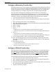
F-2 STEP1 Protocol Operation Manual • for OIT3165/4165, OIT3175/4175 and OIT3185/4185 models: • • • • 1010-0096, Rev. 04 1. While pressing and holding down the CLEAR or ENTER key, cycle power to the OIT. Continue pressing until the Disp View Angle or OIT Brightness message is displayed, then release. 2. Press the ENTER key to display Baud Rate message. 3. Press the F1 key. 4. Press the F2 key. 5. Press the F3 key. 6. Wait for a few seconds.
Appendix F: Troubleshooting F-3 3. 4. 5. 6. Press the F1 key. Press the F4 key. Press the F7 key. Wait for a few seconds. The OIT will reinitialize, allowing you to enter Local Setup by holding down the CLEAR or ENTER key. 7. Refer to Chapter 2, OIT Configuration and follow instructions. The OIT’s Keypad is Not Responding As Expected Many operating parameters affect the operation of the OIT’s keypad. Therefore, if a key is not operating as expected, consider the following: • The operating mode (i.e.
F-4 STEP1 Protocol Operation Manual This page intentionally left blank 1010-0096, Rev.
Index Index ! 3-Wire RS-485 Interactive & Block modes Limitations Network mode 5-Wire RS-485 Interactive & Block modes Network mode B Baud Rate Block Mode Disable Block Mode control command Enable Block Mode control command Keyboard Input Buffer C 30 15 19 19 15 18 24 36 A-7 A-8 36 Cable 1 Command Terminator in Control Commands A-1 in Network Mode 37 Configuration 21 Append Linefeed 28 Baud Rate 24 Block Echo 29 Cursor Type 31 Delayed Linefeed 30 Local Echo 29 Network Address 31 OIT Display Brightnes
STEP1 Protocol Operation Manual E Extended Character Sets Inserting into a Predefined Message MAP320D, OIT3200, OIT3250 MAP340D, OIT4400, OIT4450 MAP460D, OIT3100 Series, OIT3600, OIT4100 Series OIT5400 F Function Keys Configuring as Shift, Delete, Enter or Clear Disabling Displaying Predefined Messages Function Key ASCII String Function Key Control control command Momentary Momentary Tutorial Push-on/Push-off Push-on/Push-off Tutorial Screen Function Key control command Sending Message to Host Sending