
Instructions / Assembly


16
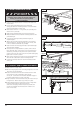
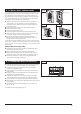
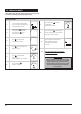
9. CONTROL UNIT CONNECTIONS
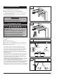
Danger of electric shock:
Before any wiring work begin, make sure that the
operator and all wiring is disconnected from the power
supply. During wiring make sure all wires remain discon-
nected from the power supply at all times.
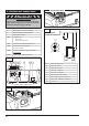
XB03 XW40 XB72
XW81
A B C
XN70
Fig. 36
Fig. 37
A GDO expansion module slot - empty
B Integrable Battery backup (optional)
C Battery backup display
XB03 Connection for
– Wall control
– Photo eye safety system
XB72 Connection for modular antenna Fig. 34
XN70 Connection for battery backup
Connections XN70
XW40
XW81
Connection for
Not available
Inputs/outputs modules connection
MS bus expansion module
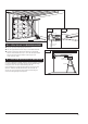
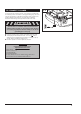
Modular Antenna Installation or Replacement
3.3.3
Fig. 38
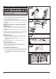
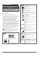
Terminal block XB03
5
4
3 2
1
Wiring Diagram
for XB03 Terminal Block
- X B0 3
12
2 1 1
TX
2
RX
- W 1
2
1
- W 2
2
1
21
- W 1
- W 2
- AP2 7
4
3
1
5
- S b1 2
Wall controI - Impulse - Conductor 1
Wall controI - GROUND - Conductor 2
4
3
5
24 V DC
2 Photo eye - Conductor 2
1 Photo eye - Conductor 1
AP27 Photo eye safety system
RX Photo eye receiver
TX Photo eye transmitter
Sb1 Impulse button - Wall Control
3.3.3
Fig. 39
Conductors/wires