Model PMD520 User Guide 3-Head Double Cassette Deck R 1
CAUTION RISK OF ELECTRIC SHOCK DO NOT OPEN CAUTION: TO REDUCE THE RISK OF ELECTRIC SHOCK, DO NOT REMOVE COVER (OR BACK) NO USER-SERVICEABLE PARTS INSIDE REFER SERVICING TO QUALIFIED SERVICE PERSONNEL The lightning flash with arrowhead symbol, within an equilateral triangle, is intended to alert the user to the presence of uninsulated “dangerous voltage” within the product’s enclosure that may be of sufficient magnitude to constitute a risk of electric shock to persons.
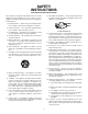
SAFETY INSTRUCTIONS READ BEFORE OPERATING EQUIPMENT 12. Grounding or Polarization — The precautions that should be taken so that the grounding or polarization means of an appliance is not defeated. This product was designed and manufactured to meet strict quality and safety standards. There are, however, some installation and operation precautions which you should be particularly aware of. 1. Read Instructions — All the safety and operating instructions should be read before the appliance is operated. 2.
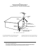
FIG.
Dolby noise reduction and HX Pro headroom extension are manufactured under license from Dolby Laboratories Licensing Corporation. HX Pro originated by Bang & Olufsen. “DOLBY” the double-D symbol and “HX PRO” are trademarks of Dolby Laboratories Licensing Corporation. is a registered trademark.
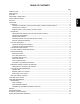
TABLE OF CONTENTS Page INTRODUCTION ............................................................................................................................................................. 6 PRECAUTIONS .............................................................................................................................................................. 6 FEATURES ......................................................................................................................................
English Thank you for selecting the Marantz Model PMD520 3-head Independent Dual Well Cassette Deck. Please read these operating instructions carefully. We recommend that you read the entire user guide before you connect or operate the unit. After you have reviewed the contents this manual, we suggest that you make all system connections before you attempt to operate the unit. Refer to the Figures on Pages 54 – 57 of this user guide. The callout numbers on the Figures correspond to those found in the text.
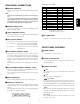
Pin No. 1 2 3 4 5 6 7 8 9 10 11 12 13 A DECK A/B LINE INPUT These jacks should be connected to LINE OUTPUT of your source. English Note: Short pins are installed from the factory in the Deck B INPUT. The short pins should be removed only if an input source is connected directly to Deck B. They have been installed to avoid crosstalk from one deck to the other, in case one deck is recording and the other deck is playing back.
r COUNTER BUTTONS i TAPE SPEED BUTTONS These switches determine the playback/recording speed of tapes in both Wells A and B. ¡ TAPE TIME This button changes the reference time of tape (tape type) so that the time counter can show accurate time information. The initial setting when the unit is turned on is "60". The first press of this button displays the current setting.
!3 TIMER DISPLAYS This switch is used to set the timer operation mode. a TAPE TIME COUNTERS ¡ OFF No timer operation is used when the switch is set to this position. These counters display the tape position for each Well in Minutes and Seconds. b BARGRAPH LEVEL METERS These meters display the signal levels for each Well in stereo. ¡ PLAY Timer playback operation is activated when the switch is set to this position. The tape will automatically start playing when the power is switched on.
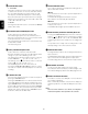
RECORDING PLAYBACK SINGLE WELL RECORDING (Same procedure for Well A or Well B) PLAYBACK ON ONE WELL (Same procedure for Well A or Well B) OR BOTH WELLS 1. Insert a blank cassette into the cassette holder(s). 1. Set the POWER button to ON. 2. Reset the tape counter by pressing the RESET button. 2. Insert a prerecorded cassette in the cassette holder(s). 3. If you wish to use Dolby NR, set the DOLBY NR switches accordingly. 3. Reset the tape counter by pressing the RESET button. English 4.
CONTINUOUS RECORDING TIMER RECORDING (Same procedure for Wells A and B) 1. Insert blank cassettes into both Wells. Be sure that both decks are rewound. 1. Connect the power cord of this unit to a timer. 2. Insert a blank cassette in the cassette holder(s). 3. Reset the tape counters to "00.00" by pressing the RESET buttons. 4. If you wish to use Dolby NR in your recording, set the DOLBY NR switches to select B- or C-type noise reduction. 4. Press the CONT button.
SYNCHRONOUS RECORDING Refer to Fig. 5 CASCADE CONTINUOUS PLAYBACK Synchronous Recording is possible only when this unit is connected with a Marantz Professional product equipped with the Sync Recording function. The Synchronous Recording connection consists of a single RCA cable which runs to the RC-5 REMOTE input jack on the rear panel of the PMD520, from the REMOTE output jack on the rear panel of the Marantz source. 1. Set the POWER button to ON. English 2.
Error Message OTHER OPERATIONS If a problem occurs during the AUTOMATIC BIAS routine, an Error message will appear on the display. Please refer to the following table. ¡ If you must stop playback or recording in the middle of a tape, be sure to press the STOP button first, then turn the power off. If the power is turned off in the middle of an operation, the cassette tape remains loaded, and it may be impossible to eject.
DUPLICATION SYNCHRONIZATION HIGH SPEED DUPLICATION Refer to Fig. 6 CONNECTION 1. Insert the master tape in Well A of unit #1. 2. Insert the blank cassettes in both Wells A and B of units #2 and after. 1. Connect the WRC220 * to the RC-5 IN jack of unit #1. 3. Press the TAPE SPEED HIGH buttons of all the units so that the HIGH indicators of all the units light up. 2. Connect the RC-5 OUT jack of unit #1 with the RC-5 IN jack of unit #2. English 5. Press the A+B button of the WRC220.
Medium-frequency gain The internal oscillator outputs a 3 kHz signal in the range of ± 4 dB. This signal is recorded and played to adjust the recording gain at around 3 kHz so that the playback output becomes the standard level as shown by B in Figure 3. AUTO BIAS & EQ SYSTEM System Operation Description This system sets the recording bias, recording gain, mediumfrequency gain, high-frequency gain and high-frequency peak automatically so that the characteristics of the tape in use can be exhibited fully.
REPAIRS This section describes the care and maintenance tasks that must be performed to optimize the operation of your Marantz equipment. Only the most competent and qualified technicians should be allowed to service your unit. Marantz and its factory trained warranty station personnel have the knowledge and special equipment needed for repair and calibration of this precision instrument.
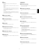
RC-5 Command Table TECHNICAL SPECIFICATIONS Command RC-5 Code Track System ........................................... 4 Track, 2 Channel Head System 0 1 1800 1801 Rec Play Head ........................................ Hard Permalloy Erase Head ........................................... Dual Gap Ferrite 2 3 1802 1803 Approx Head Life .................................................. 1000H Recording/Erasure System ........................ AC 105 kHz Bias 4 5 1804 1805 Motor System Capstan ....
Figure 4 ∼ R MODEL NO. PMD520 AC120V 60Hz 0.25A DECK B LINE OUT DECK A LINE OUT IN MADE IN JAPAN LOOP THROUGH A OUT REMOTE IN L RC-5 L L R R IN INPUT SELECT A.
CASCADE OPERATION Figure 5 IN 1 MIC IN 2 IN 3 OUT MIXER ∼ R MODEL NO. PMD520 AC120V 60Hz 0.25A DECK B LINE OUT DECK A LINE OUT IN MADE IN JAPAN LOOP THROUGH A OUT REMOTE IN L RC-5 L L R R INPUT SELECT A. B A R EXT IN CONTROL I / O MPX FILTER ON OFF OUT ∼ R MODEL NO. PMD520 AC120V 60Hz 0.25A DECK B LINE OUT DECK A LINE OUT IN MADE IN JAPAN LOOP THROUGH A OUT REMOTE RC-5 IN L L L R R INPUT SELECT A.
DUPLICATION SYNCHRONIZATION WRC220 Figure 6 TAPE A TAPE B CD A B CD AUTO TAPE A TAPE B CD AUTO REW 1× 2× PLAY STOP NORMAL SPEED HIGH SPEED PREV REW FF NEXT BIAS RECORD A+B RECORD RECORD MUTE AUTO BIAS UNIT #1 ∼ R M O DEL NO . PM D5 2 0 AC1 2 0 V 6 0 Hz 0 .2 5 A DECK B LINE OUT DECK A LINE OUT IN MADE IN JAPAN LOOP THROUGH A OUT REMOTE IN L RC-5 L L R R INPUT SELECT A. B A R EXT IN CONTROL I / O MPX FILTER ON OFF OUT UNIT #2 ∼ R M O DEL NO .
Metal tape detection hole High tape detection hole Figure 7 Figure 8 Figure 9 Be sure to close the casette holder cover when the unit is not to be used for a long period of time.