Model PM-15S2 User Guide Integrated Amplifier
CAUTION RISK OF ELECTRIC SHOCK DO NOT OPEN CAUTION: TO REDUCE THE RISK OF ELECTRIC SHOCK, DO NOT REMOVE COVER (OR BACK) NO USER-SERVICEABLE PARTS INSIDE REFER SERVICING TO QUALIFIED SERVICE PERSONNEL The lightning flash with arrowhead symbol within an equilateral triangle is intended to alert the user to the presence of uninsulated “dangerous voltage” within the product’s enclosure that may be of sufficient magnitude to constitute a risk of electric shock to persons.
IMPORTANT SAFETY INSTRUCTIONS READ BEFORE OPERATING EQUIPMENT This product was designed and manufactured to meet strict quality and safety standards. There are, however, some installation and operation precautions which you should be particularly aware of. 1. Read these instructions. 2. Keep these instructions. 3. Heed all warnings. 4. Follow all instructions. 5. Do not use this apparatus near water. 6. Clean only with dry cloth. 7. Do not block any ventilation openings.
ENGLISH WARRANTY For warranty information, contact your local Marantz distributor. RETAIN YOUR PURCHASE RECEIPT Your purchase receipt is your permanent record of a valuable purchase. It should be kept in a safe place to be referred to as necessary for insurance purposes or when corresponding with Marantz. IMPORTANT When seeking warranty service, it is the responsibility of the consumer to establish proof and date of purchase. Your purchase receipt or invoice is adequate for such proof. FOR U.K.
CE MARKING English The PM-15S2 is in conformity with the EMC directive and low-voltage directive. Français Le PM-15S2 est conforme à la directive EMC et à la directive sur les basses tensions. Deutsch Das Modell PM-15S2 entspricht den EMC-Richtlinien und den Richtlinien für Niederspannungsgeräte. Nederlands De PM-15S2 voldoet aan de EMC eisen en de vereisten voor laag-voltage. Italiano Il PM-15S2 è conforme alle direttive CEE ed a quelle per i bassi voltaggi.
ENGLISH FRANÇAIS DEUTSCH NEDERLANDS ITALIANO ENGLISH NOTA SUL RICICLAGGIO I materiali di imballaggio di questo prodotto sono riciclabili e possono essere riutilizzati. Questo prodotto e gli accessori in dotazione con esso, eccettuate le batterie, rappresentano il prodotto applicabile per la direttiva RAEE (rifiuti di apparecchiature elettriche ed elettroniche). Smaltirli seguendo le proprie normative locali sul riciclaggio.
Before use, check the below accessories were included in the package. • Remote controller ............................................................. 1 • AC Power cord ................................................................. 1 • Size “AAA” batteries ......................................................... 2 • User Guide ....................................................................... 1 • Warranty Card (U.S.A) U.S.A. ......................................................................
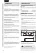
ENGLISH NAMES AND FUNCTIONS FEATURES The PM-15S2 is a successor model for the PM-15S1, adopting leading-edge technologies developed for the higher-grade PM-11S2 model. ¶ HDAM-SA3 Module BASIC CONNECTIONS The HDAM-SA3 is a key amplifier module for a current feedback amplifier and is mounted on the voltage-current conversion block, which is the most important part of an amplifier, for further improved circuit stability and high-speed processing.
USAGE OF REMOTE CONTROLLER Operational range Operate the unit with the remote controller within the range of the illustration below. Loading batteries Before using the remote controller for the first time, load the batteries in the remote controller. The batteries provided are used to verify the operations of the remote controller only. Paying close attention to polarity indicators (ª plus and · minus), be sure to insert batteries correctly and as indicated. Approx. 5 m (16.
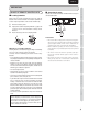
ENGLISH NAMES AND FUNCTIONS NAMES AND FUNCTIONS FRONT PANEL q w e r t yu i o BASIC CONNECTIONS !0 !4 !3 !1 !0 BASIC OPERATIONS ADVANCED CONNECTIONS q INPUT SELECTOR Knob i ATT Button This knob is for selecting the input source to use in playback and recording. The selected input source is displayed in the display. This button attenuates the volume with one press of the button. For instructions on How to Set the Attenuation Level, see page. 19.
OPERATE !7 0.5dB Steps !5 Power Indicator This indicator is lit a blue color while power to the unit is ON. Turn the VOLUME knob on the unit to the left, or press the VOLUME ∞ button on the remote controller. !6 Display Panel Approximately 3 seconds after the power to the unit is activated, the ID number is displayed here. Min After that, the top line displays the selected input source, and the bottom line displays the volume level. The volume attenuation (dB units) is displayed.
ENGLISH NAMES AND FUNCTIONS NAMES AND FUNCTIONS z Input Selector Buttons REMOTE CONTROLLER BASIC CONNECTIONS This remote controller can be used to control the PM-15S2 and Marantz Super Audio CD players or DVD players that have a remote control receptor. The operations possible by remote control may differ with each component, therefore see the instruction manual that came with the component. These buttons are for selecting the input source to use in playback.
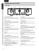
P.DIRECT IN PRE OUT o F.C.B.S. L L SPEAKER SYSTEMS L SPEAKER IMPEDANCE : 4 - 8 OHMS R IN R R CH L L R IN OUT L CH 1 RECORDER 2 R IN IN R IN 1 LINE 2 BI.AMP STEREO IN OUT !2 !1 IN OUT !0 q PHONO GND Terminal u AMP MODE Switch Connect the grounding wire from an analog record player here. STEREO : Set to use this unit as a normal two-channel stereo amplifier. BI-AMP : Set to use this unit in complete bi-amp connection. For STEREO COMPLETE BI-AMP mode, see page 13.
ENGLISH NAMES AND FUNCTIONS BASIC CONNECTIONS CONNECTING AUDIO COMPONENTS Notes: BASIC CONNECTIONS • Do not connect this unit and other components to mains power until all connections between components have been completed. • Insert all plugs and connectors securely. Incomplete connections may make noise. • Be sure to connect the left and right channels properly. Red connectors are for the R (right) channel, and white connectors are for the L (left) channel.
CONNECTING SPEAKER SYSTEMS • Be sure to use speakers with the specified impedance as shown on the rear panel of this unit. Note: • To prevent damage to circuitry, do not let the bare speaker wires touch each other and do not let them touch any metal part of this unit. BASIC CONNECTIONS BASIC CONNECTIONS NAMES AND FUNCTIONS ENGLISH • Do not connect two or more speaker cables to a speaker terminal at the same time. If you do so, this unit may be damaged.
ENGLISH NAMES AND FUNCTIONS BASIC OPERATIONS BASIC CONNECTIONS 7 1. Wiring speaker cable Strip away approx. 10 mm (3/8 inch) of wire insulation. AMP OPERATION 7 Turning the Unit ON 10 mm (3/8 in) BASIC CONNECTIONS 2. Twist the bared wire ends tight, to prevent short circuits. 3. Loosen the knob by turning it counterclockwise. POWER ON/OFF button BASIC OPERATIONS 4. Insert the bare part of the wire into the hole in side of each terminal. 1.
BASIC OPERATIONS 7 Volume Adjustment Adjust the volume as desired with the VOLUME knob on the front panel or the VOLUME 3 or 4 button on the remote controller. Attenuating the Volume Level Temporarily The volume level from the speakers can be temporarily attenuated.
ENGLISH NAMES AND FUNCTIONS ADVANCED CONNECTIONS CONNECTION TO THE P.DIRECT IN JACKS If an AV amplifier or preamplifier is available, this unit can be used as a power amplifier, using the connections shown below. For this use, hold the P.DIRECT IN button on the front panel of this unit pressed for at least 3 seconds to set it to ON. “POWER AMP DIRECT” is displayed on the display. BASIC CONNECTIONS For details on preamplifier operations, refer to the operation manual of the preamplifier.
STEREO COMPLETE BI-AMP CONNECTION 1. The two amplifiers are connected by F.C.B.S. for synchronized use. For F.C.B.S. connection, connect with commercially available monaural ⇔ monaural miniplugs or stereo ⇔ stereo miniplugs as described in F.C.B.S. (page. 16). 2. Set the ID numbers as explained in HOW TO SET ID NUMBERS (page. 17). When the ID1 amplifier is operated, the ID 2 amplifier will operate in sync. Set the AMP MODE switch on the rear panel to BI-AMP, referring to BI-AMP MODE (page 17). 3.
ENGLISH NAMES AND FUNCTIONS ADVANCED CONNECTIONS 7 Speaker positioning for Super Audio multi-channel sound BASIC CONNECTIONS In order to enjoy Super Audio CD multi-channel sound with the best possible acoustics, it is recommended to position speakers as specified in ITU-R BS.775-1 of the International Telecommunication Union (ITU). Super Audio CD multi-channel discs are recorded and mixed so as to achieve the optimum effect with a speaker system laid out as specified in ITU-R BS.775-1.
ADVANCED CONNECTIONS BASIC CONNECTION FOR 5.1 MULTI-CHANNEL PLAYBACK 1. The three units are connected using F.C.B.S. For the F.C.B.S connection, prepare 3 audio connection cables, and refer to F.C.B.S. on page 16. 2. Set the ID numbers for the three amplifiers as explained in HOW TO SET ID NUMBERS (page. 17). BASIC CONNECTIONS When the ID 1 unit is operated, ID 2 and ID 3 units will operate in sync. Connect the outputs of players that have 5.1 channel analog outputs to each of the three units.
ENGLISH NAMES AND FUNCTIONS ADVANCED CONNECTIONS F.C.B.S. BASIC CONNECTIONS F.C.B.S. (Floating Control Bus System) is a communication system that connects up to four PM-15S2s over a dedicated bus line so as to enable synchronized operations amongst them via 2-way data communications. Prepare the correct number of portable audio connection cables for the number of units to be connected. Any of the following two types of connecting cables can be used.
The ID number of the unit appears on the display for about 3 seconds after the power is activated. When multiple PM-15S2s are connected, a unique ID number must be set of each one in order to distinguish between them. The unit that centrally controls the other units takes ID 1. The unit with ID1 is called the “Master”. The other units that synchronize with the master are called “slaves” and take IDs “2” ~ “4”. INPUT SELECTOR Knob BI.
ENGLISH NAMES AND FUNCTIONS BASIC CONNECTIONS BASIC OPERATIONS ADVANCED CONNECTIONS ADVANCED OPERATIONS TROUBLESHOOTING OTHERS 18 ADVANCED OPERATIONS 7 TRIMMING LEVEL trimming that adjusts the volume level on left and right channels Note: How to Trim Volume Level The volume level of the left and right channels can be trimmed in 0.5dB steps across a 0.0 to -9.0dB range. When the unit is shipped from the factory, the volume level is set to 0.0dB (maximum).
ADVANCED OPERATIONS ATT (ATTENUATION) 2. The attenuation level setting value changes with each press of the ATT button on the unit. 3. When the desired attenuation level setting appears on the display, leave it unchanged for 2 seconds or longer to enter the setting. Once entered, the display returns to the volume level indication. ATT button VOLUME ATT is a one-touch feature for reducing the volume level.
ENGLISH NAMES AND FUNCTIONS ADVANCED OPERATIONS CONTROLLING MARANTZ COMPONENTS 1. 2. Press the desired SOURCE button. Press the desired operation buttons to play the selected component. • For details, refer to the component’s user guide. BASIC CONNECTIONS • It may not be possible to operate some models.
The batteries of the remote controller are exhausted. The remote controller is located outside its operable range. Some object is placed between the unit and remote controller. The remote sensor of the unit is exposed to strong light. Page 10 10 Replace with new batteries. 3 Check the operable range of the remote controller and use it within that range. 3 Remove the object. 3 Avoid exposing the remote sensor to the strong light. Check the connection between the Speaker connection is incomplete.
ENGLISH NAMES AND FUNCTIONS BASIC CONNECTIONS BASIC OPERATIONS ADVANCED CONNECTIONS ADVANCED OPERATIONS TROUBLESHOOTING OTHERS 22 TROUBLESHOOTING PHONO Symptom Cause Grounding connection from the record player is improper. Noise occurs during record Connection to the PHONO IN jacks is incomplete. playing. Or, no sound is heard. A TV set, etc. placed too close to the record player may affect the sound. The PHONO MC button is not set properly for the cartridge used.
1 ERROR 02 2 ERROR 03 3 ERROR 04 ¶ In the event of overcurrent The protection circuit is activated if current exceeding a certain level is detected, which can happen if excessive signal flow is input to the amplifier or if the unit is connected to a speaker system of less than 4 1 impedance. The protection circuit is also activated if a speaker cable shorts. ¶ If excessive ultrabass signals are input The protection circuit is also activated if ultrabass signals are input.
ENGLISH SPECIFICATIONS ADVANCED CONNECTIONS ADVANCED OPERATIONS DIMENSIONAL DRAWINGS TROUBLESHOOTING (Unit: mm (in)) 19 (3/4) 105 (4-3/16) 123 (4-7/8) OTHERS Weight : 18.5 kg (40.8 lbs) 24 440 (17-3/8) 18 (3/4) BASIC OPERATIONS Specifications subject to change without prior notice. 25 (1) BASIC CONNECTIONS Power output (20 Hz – 20 kHz simultaneous drive of both channels) (81 load) ...............................................................................................................
• wipe the equipment with the damp cloth. • dry the equipment by wiping it with a dry cloth. USING HEADPHONES If the volume in the headphones is too high, it may injure your ears. Do not set the sound volume too high. BASIC CONNECTIONS BASIC OPERATIONS • dip a soft, lint free in the solution and wring the it is damp. ADVANCED CONNECTIONS • dilute some washing up liquid in water, in a ratio of one part detergent to six parts water.
Memo
www.marantz.com You can find your nearest authorized distributor or dealer on our website. is a registered trademark.
lDapantz® MARANTZ CANADA LIMITED WARRANTY Marantz Canada ("Marantz") warrants the following Marantz products for the periods indicated: Who May Enforce the Warranty 3-year warranty for both Parts & Labour I from the original purchase date: What We Will Pay For Only the original purchaser may enforce this warranty. We will pay for all labor and material expenses for items covered by the warranty. Payment of shipping charges is discussed in the next section of this warranty.
_apantz® GARANTIE LlMITEE DE MARANTZ CANADA Marantz Canada ("Marantz") garantie les produits suivants pour les periodes indiquees : 3 ans de garantie pour les pieces et la main d'muvre prenant effet it partir de la date d'achat du produit : Amplificateurs, Preamplificateurs, Pre-ampli-processeurssyntoniseurs; amplificateurs integres, syntoniseurs, recepteurs, lecteurs DVD, enregistreurs CD, lecteurs CD, platines a cassette audio, telecommandes programmables, Dock universe!, systeme de cinema a domicile, ca
For U.S.A. _arantz® Limited Warranty Marantz America, Inc. ("Marantz") warrants the following Marantz Products for the periods indicated: Who may enforce the warranty This warranty may be enforced only by the original purchaser. 1.