
Service manual


4
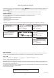
NOTE FOR PARTS LIST
The suppliers and their type numbers of fusible resistors
are as follows;
1. KOA Corporation
Part No. (MJI) Type No. (KOA) Description
00MNH05
×
×
×
140 RF25S
×
×
×
×
Ω
J (±5% 1/4W)
00MNH05
×
×
×
120 RF50S
×
×
×
×
Ω
J (±5% 1/2W)
00MNH85
×
×
×
110 RF73B2A
×
×
×
×
Ω
J (±5% 1/10W)
00MNH95
×
×
×
140 RF73B2E
×
×
×
×
Ω
J (±5% 1/4W
)
2. Matsushita Electronic Components Co., Ltd
Part No. (MJI) Type No. (MEC) Description
00MNF05
×
×
×
140 ERD-2FCJ
×
×
×
(±5% 1/4W)
00MRF05
×
×
×
140
00MNF02
×
×
×
140
ERD-2FCG
×
×
×
(±2% 1/4W)
00MRF02
×
×
×
140
Examples ;
*
Resistance value
0.1
Ω
.....001 10
Ω
.....100 1k
Ω
..... 102 100k
Ω
.... 104
0.5
Ω
.....005 18
Ω
.....180 2.7k
Ω
..... 272 680k
Ω
.... 684
1
Ω
.....010 100
Ω
.....101 10k
Ω
..... 103 1M
Ω
.... 105
6.8
Ω
.....068 390
Ω
.....391 22k
Ω
..... 223 4.7M
Ω
.... 475
NOTE ON FUSE :
Regarding to all parts of parts code 00MFS20xxx2xx, replace
only with Wickmann-Werke GmbH, Type 372 non glass type fuse.
NOTE ON SAFETY FOR FUSIBLE RESISTOR :
▲ ▲
▲▲
Resistance value
Resistance value
(0.1
−
10k
Ω
)
▲
▲
Resistance value
Resistance value
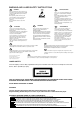
ANT. : ANTENNA BATT. : BATTERY
CAP. : CAPACITOR CER. : CERAMIC
CONN. : CONNECTING DIG. : DIGITAL
HP : HEADPHONE MIC. : MICROPHONE
µ-PRO : MICROPROCESSOR REC. : RECORDING
RES. : RESISTOR SPK : SPEAKER
SW : SWITCH
TRANSF.
: TRANSFORMER
TRIM. : TRIMMING TRS. : TRAMSISTOR
VAR. : VARIABLE X’TAL : CRYSTAL
NOTE ON SAFETY :
Symbol z Fire or electrical shock hazard. Only original parts
should be used to replaced any part marked with symbol z.
Any other component substitution (other than original type), may
increase risk of re or electrical shock hazard.
安全上の注意 :
z がついている部品は、安全上重要な部品です。必ず指定
されている部品番号の部品を使用して下さい。
ABBREVIATION AND MARKS
}
}
}
}
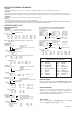
PARTS INFORMATION
RESISTORS
1) 00MGD05
× × ×
140, Carbon lm xed resistor, ±5% 1/4W
2) 00MGD05
× × ×
160, Carbon lm xed resistor, ±5% 1/6W
Examples ;
Resistance value
0.1
Ω
.....001 10
Ω
.....100 1k
Ω
..... 102 100k
Ω
..... 104
0.5
Ω
.....005 18
Ω
.....180 2.7k
Ω
..... 272 680k
Ω
..... 684
1
Ω
.....010 100
Ω
.....101 10k
Ω
..... 103 1M
Ω
..... 105
6.8
Ω
.....068 390
Ω
.....391 22k
Ω
..... 223 4.7M
Ω
..... 475
Note : Please distinguish 1/4W from 1/6W by the shape of parts
used actually.
CAPACITORS
CERAMIC CAP.
3) 00MDD1
×
×
×
×
370, Ceramic capacitor
Disc type
Temp.coeff.P350
~
N1000, 50V
Examples ;
Tolerance (Capacity deviation)
±0.25pF...... 0
±0.5pF...... 1
±5%...... 5
Tolerance of COMMON PARTS handled here are as follows :
0.5pF
~
5pF .....±0.25pF
6pF
~
10pF .....±0.5pF
12pF
~
560pF .....±5%
Capacity value
0.5pF .....005 3pF .....030 100pF .....101
1pF .....010 10pF .....100 220pF .....221
1.5pF .....015 47pF .....470 560pF ..... 561
C
ERAMIC CAP.
4) 00MDK16
× × ×
300, High dielectric constant ceramic
capacitor
Disc type
Temp.chara. 2B4, 50V
Examples ;
Capacity value
100pF .....101 1000pF ..... 102 10000pF .....103
470pF .....471 2200pF ..... 222
ELECTROLY CAP. ( )
5) 00MEA
× × × × × ×
10, Electrolytic capacitor
One-way lead type, Tolerance ±20%
Examples ;
Capacity value
0.1µF ..... 104 4.7µF .....475 100µF ... 107
0.33µF ..... 334 10µF .....106 330µF ... 337
1µF ..... 105 22µF .....226 1100µF ... 118
2200µF ... 228
Working voltage
6.3V .....006 25V .....025
10V ..... 010 35V .....035
16V ..... 016 50V .....050
FILM CAP. ( )
6) 00MDF15
× × ×
350 Plastic lm capacitor
00MDF15
× × ×
310 One-way type, Mylar ±5% 50V
00MDF16
× × ×
310 Plastic lm capacitor
One-way type, Mylar ±10% 50V
Examples ;
Capacity value
0.001µF (1000pF) ...........102 0.1µF .... 104
0.0018µF ...........................182 0.56µF .... 564
0.01µF ...........................103 1µF .... 105
0.015µF ...........................153
}
Capacity value
Tolerance
Capacity value
Resistance value
Working voltage
Capacity value
▲
▲
Capacity value
}
}
}
}
}
060522 MZ
NOTE FOR SCHEMATIC DIAGRAM
WARNING:
Parts marked with this symbol
z
have critical characteristics. Use ONLY replacement parts recommended by the manufacture
r.
CAUTION:
Before returning the unit to the customer, make sure you make either (1) a leakage current check or (2) a line to chassis resistance check. If the
leakage current exceeds 0.5 milliamps, or if the resistance from chassis to either side of the power cord is less than 460 kohms, the unit is defective.
WARNING:
DO NOT return the unit to the customer until the problem is located and corrected.
NOTICE:
ALL RESISTANCE VALUES IN OHM. k=1,000 OHM / M=1,000,000 OHM
ALL CAPACITANCE VALUES IN MICRO FARAD. P=MICRO-MICRO FARAD EACH VOLTAGE AND CURRENT ARE MEASURED AT NO SIGNAL
INPUT CONDITION. CIRCUIT AND PARTS ARE SUBJECT TO CHANGE WITHOUT PRIOR NOTICE.