Service Manual DV4000/F1N, /K1G /N1B, /S1G, /U1B DVD Player PLAY DVD PLAYER DV4000 OPEN / CLOSE STANDBY / ON DTS SURROUND PAUSE WIDE DOLBY DIGITAL DIMMER POWER SPATIALIZER PREV NEXT MPEG STOP TABLE OF CONTENTS 1. 2. TECHNICAL SPECIFICATION ............................................................................... 1 CONNECTION FACILITIES .................................................................................... 2 3. 4. INFORMATIONS ..............................................
MARANTZ DESIGN AND SERVICE Using superior design and selected high grade components, MARANTZ company has created the ultimate in stereo sound. Only original MARANTZ parts can insure that your MARANTZ product will continue to perform to the specifications for which it is famous. Parts for your MARANTZ equipment are generally available to our National Marantz Subsidiary or Agent. ORDERING PARTS : Parts can be ordered either by mail or by Fax.. In both cases, the correct part number has to be specified.
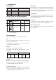
1. TECHNICAL SPECIFICATIONS Discs played DVD video disc ................................................... 12 cm single sided, single layer 12 cm single sided, double layer 12 cm double sided, single layer 12 cm double sided, double layer (one layer per side) 8 cm single sided, single layer 8 cm single sided, double layer 8 cm double sided, single layer 8 cm double sided, double layer (one layer per side) Compact disc (CD-DA, Video CD) .............................................12 cm, 8 cm Video system..
2. CONNECTION FACILITIES 2.1 Video performance (/N1B only) 1 - Pin 15 - Pin 16 3 5 7 9 11 13 15 17 19 21 Red out :0.7Vpp ( 0.1V into 75 Ohm (*) fast switching RGB/ CVBS : <0.4V into 75 Ohm = CVBS <1V/ <3V into 75 Ohm = RGB 2 4 6 8 10 12 14 16 18 20 - 2.1.1 SCART - Pin 1 Pin 2 Pin 3 Pin 4 Pin 5 Pin 6 Pin 7 Pin 8 Audio R out :1.8V RMS not connected Audio L out :1.8V RMS GND GND not connected Blue out :0.7Vpp ( 0.1V into 75 Ohm (*) funcion switching : 2V TV >4.5V / <7V asp. ratio 16:9 DVD >9.
3. INFORMATIONS Multi-angles: REGION CODE VERSION REGION CODE COUNTRY /FXX /KXX 2 6 JAPAN CHINA /NXX /SXX 2 3 EUROPE SINGAPORE/HONGKONG /UXX 1 USA/CANADA On some DVDs, scenes have been filmed from different angles (up to a maximum of 9). On these discs, you can select the angle that you want to watch. Please refer to the DVD’s manual to see which scenes have multi-angles.
4. SERVICING HINT SERVICE HINTS SERVICE TOOLS Audio signals disc Disc without errors (SBC444)+ Disc with DO errors, black spots and fingerprints (SBC444A) Disc (65 min 1kHz) without no pause Max. diameter disc (58.
5. DISASSEMBLY In case of trouble, etc., necessitating dismantling, please dismantle in the order shown in the illustrations. Reassemble in the reverse order. 1. Removal of the UPPER COVER 2. Removal of the FRONT PANEL 1) Press the “EJECT” button while the unit’s power is turned on and open the DISC TRAY. 2) Remove the decoration plate on the DISC TRAY by pulling it upward. 3) Remove the three retaining screws on the bottom and two screws on each left and right side of the FRONT PANEL as shown.
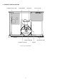
6. PRINCIPAL PARTS LOCATION POWER SUPPLY PCB SLED MOTOR MAIN PCB OUTPUT PCB SPINDLE MOTOR LOADING MOTOR Fig.
7. REPLACEMENT OF PRINCIPAL COMPONENTS 7-1. Removal of the TRAVERSE MECHA. 7-1-2. Removal of the TRAVERSE MECHA. 7-1-1. Removal of the MECHANISM BLOCK 1) Turn the unit’s power on and press the “EJECT” button to 1) Remove the four b screws on the MAIN PCB and then disconnect the P800 connector on the MAIN PCB. eject the DISC TRAY. 2) Disconnect the power cord and remove the DISC CLAMPER BLOCK. 3) Completely remove the DISC TRAY by pulling it outwards while pulling up both of the stopper tabs alternately.
3) Carefully disconnect the two connectors (P500, P600) and the two flat cables (P200, P300) on the MECHANISM PCB. 7-3. Replacement of the PICK UP BLOCK Replacement of the PICK UP BLOCK itself is not recommended because its azimuth adjustment is very critical and requires a special jig. If PICK UP BLOCK replacement is necessary, replace with an entire TRAVERSE MECHANISM only. P600 P200 P300 P500 Fig. 7-6 4) Using tweezers, release the four retaining HOOKs of the TRAVERSE MECHA.
8. SERVICE MODE 8-1 OPERATION 8-1. 8-1-1. Main Microprocessor (IC600 : MB90574) Functions which operated by main microprocessor are follows. Control of following IC's. AV decoder, DEM/ECC, VIDEO encoder, CDDSP, AUDIO-DAC, PRE-AMP, READ-CHANNEL, SERVO Mechanism control DVD rate control OSD control DISC detect, Focus/Tracking alignment Data transmission between OPE microprocessor 8-1-1.
8-1-2. OUTPUT CONTROL OUTPUT CONTROL 8-1-2. Output Control Microprocessor (IC700:M38022) Main operation features of this microprocessor is as follows. Power supply control : Power efficiency switching. 3.3V line ON/OFF 5.0V line ON/OFF 9.0V line ON/OFF Out put selection of the OUTPUT PCB.
While VCD and CD Video playback / VCD/CD (CPU : In case of some fault has happened. (caused with communications between CPU: IC600 and related IC's) Some Error code is shown on the FLD. Each Error codes are described on the table 8-1. ERORR CODE 16 17 18 19 20 32 33 34 35 36 37 38 IC600 ) IC FLD 8-1 ERORR DESCRIPTION / No access with CD-DSP (IC490). CD-DSP(IC490) Sledge motor is not working. DISC D/V/C D/V/C Tracking ON error. D/V/C Focus ON error. D/V/C Sub code read error.
3. Press the " " (STOP) button while close the disctray without any disc. Then all segments of the FLD right ON. 3. (STOP) FLD 4. Press the " " (STOP) button again. The FLD indication shows below. Then the laser diode for DVD will right ON. 4. 5. Press the " " (STOP) button again. The FLD indication shows below. Then the laser diode for CD will right ON. 5. 6. Press the " " (STOP) button again. Then the TEST MODE back to the first step. 6. 7.
8-3. EEPROM initialize The memory device (EEPROM) which used in this DVD player is programmed each functions by products regions at factory. When that EEPROM (MAIN P.C. Board IC602 : M24C16MN6T) or MAIN P.C. Board has exchanged, EEPROM initialization is necessary. If that the initialization will not be done correctly, the product might not be work correctly. The initialize procedure are as follows. 1. Remove any Disc from the tray, and turn OFF the mains power.
7. Turn ON the mains power while depress the “ DIMMER “ and “ “ (Reverse skip) buttons together. Then the FLD shows “ -- -- -- -- “. 8. Send the commands “ 1999 “ by the remote controller. (Press buttons “ 1 “, “ 9 “, “ 9 “ and “ 9 “.) Then the FLD shows “ A-00 D-XX “. (XX = is depended on EEPROM status) 9. Send the commands “ D-XX “ (Data) as your product version shows in following table by the remote controller. Data U1B F1N N1B S1G K1G 01 02 02 04 20 10.
9. ELECTRICAL ADJUSTMENT VR120 P807 TP120 P804 P800 P803 TP105 TP107 TP300 VR121 TP201 VR110 JITTER ADJ SCREW A JITTER ADJ SCREW B VR202 Fig. 9-1 9-1. DVD JITTER ADJUSTMENT 1. Stick the provided small round sticker (0.1 mm thickness) 2. Set the oscilloscope to the DC input mode and connect it to the TP201 (HOT) and the TP102 (D.GND) on the MAIN at the innermost position of a DVD disc as shown and make a swayed DVD disc. PCB. 3. Adjust the VR202 so that the DC level is minimum.
10.
AUDIO Not for /N1B /N1B ONLY Not for DV4000 18 19
VIDEO /N1B ONLY 20 21
11.
12.
OUTPUT-2-2 Not for DC4000 26 27
OUTPUT TOP VIEW TR110 IC200 TR200 OUTPUT BOTTOM VIEW TR320 TR350 TR361 TR310 TR360 TR321 TR900 TR902 TR901 TR421 TR531 TR530 TR482 TR450 28 IC719 IC700 IC470 IC520 IC570 IC420 TR400~TR405 IC340 TR500~TR505 TR540~TR542 29 TR130~TR133 IC250
OPERATION Not for DV4000 30 31
OPERATION TR101 TR102 PH100 PH120 32 33
POWER 34 35
POWER IC501 36 PH500 PH501 TR558 TR551 IC551 IC556 IC555 TR550 37 IC553 TR559 TR560
(VERS. :VERSION, U:U.S.A., F:JAPAN, K:FAR EAST, **:EUROPE) 13. EXPLODED VIEW AND PARTS LIST POS. NO VERS.
14. ELECTRICAL PARTS LIST NOTE ON SAFETY FOR FUSIBLE RESIST OR : ASSIGNMENT OF COMMON PARTS CODES. RESISTORS R R The suppliers and their type numbers of fusible resistors are as follows ; 1 . KOA Corporation Part No.(MJI) Type No.
(VERS. :VERSION, U:U.S.A., F:JAPAN, K:FAR EAST, **:EUROPE) POS. NO VERS. COLOR PART NO. (FOR PCS) OPERATION CIRCUIT BOARD DIODES 1SS133T-77 T26 1SS133T-77 T26 MTZJ4.7C T26 MTZJ2.0B T26 LED SEL5421ETP15 LED SEL5421ETP15 LED SEL5421ETP15 LED SEL2910ATP6 ORANGE LED SEL2910ATP6 ORANGE LED SPR325MVWT31 MTZJ2.
(VERS. :VERSION, U:U.S.A., F:JAPAN, K:FAR EAST, **:EUROPE) POS. NO TR404 TR405 TR420 TR421 TR450 TR482 TR500 TR501 TR502 TR503 TR504 TR505 TR530 TR531 TR540 TR541 TR542 TR580 TR581 TR582 TR900 TR901 TR902 VERS. COLOR /N1B /N1B /N1B /N1B /N1B /N1B /N1B /N1B /N1B /N1B /N1B /N1B /N1B /N1B J200 J500 /N1B L250 PJ250 PJ300 /F1N,/K1 G,/S1G /U1B PJ400 PJ900 SW900 X722 PART NO. (FOR PCS) DESCRIPTION PART NO.
<> This service manual explains the product DV4000 which mounted the DVD module TKM1000MZ with the main board only. Products which mounted are as follows. (see table) All other products have mounted main board. Spare parts for main board are not available. In case of defects are found with the main board, complete DVD module must be replaced by the TKM1000MZ with the main board .
15.
MAIN-2/3 15-3 15-4
MAIN-3/3 Not for DV4000 15-5 15-6
MAIN TOP VIEW TR113 TR100 ~TR106 IC111 TR120 TR115 IC122 IC121 IC120 TR201 TR202 15-7 TR802 TR801 TR804 ~TR806 TR190 IC202 IC203 TR300 TR200 IC311 IC607 IC507 IC503 IC610 ~IC613 TR500 IC502 IC702 15-8 IC501
MAIN BOTTOM VIEW IC701 IC700 IC500 IC550 IC614 15-9 IC851 IC606 IC703 IC602 IC605 IC852 TR490 TR491 IC490 IC850 IC600 TR600 IC603 IC300 IC201 IC801 IC901 IC800 IC803 TR117 TR167 IC802 IC991 TR112 IC110 IC100 TR170 ~TR712 IC911 IC971 TR114 IC951 TR111 IC931 TR110 15-10 TR125
MECHA 15-11 15-12
MECHA TOP VIEW TR90 TR37 MECHA BOTTOM VIEW TR34 TR33 IC1 TR1 TR35 LOADING MT100 15-13 15-14 TR36 IC2 IC4 IC3 TR32 TR31
VCD7 98 99 92 1 VIN4 VIN3 VIN2 90 91 VIN1 89 2 SP-N 67 3 8 8 4 LPC 5 A3 VIN4 VIN2 VIN3 VIN1 A1 6 A2 83 82 A4 7 VREF VGA VCD VCD VCD VCD 14 8 16 VCD VCD VCD VCD RF1 81 8 8 10 10 RFAS3 RF-VCD2 RF-VCD1 13 VREF A4 A3 A2 A1 69 65 63 64 9 FEO 11 10 12 15 17 FE TP-AMP LDON SRV FULL RF ADD1 A4 A3 A2 A1 RF ENV 18 19 20 21 22 26 TE AGC 27 10 62 60 59 28 23 24 25 10k POF 25uF 30k 32 POF-NEG BDO BDOIN BDOV1 CBDO 61 SIN/COS DDS
52 53 54 55 56 57 58 59 60 61 62 63 64 AGC-CAP AGCVRF VDD AGCLVL VSS AGCINN AGCINP VMIDI LOENV VIN HIENV RSLICE RIREF 15-17 VBG 1 VBG 49 50 51 JZ3V LZ3V VSS RIREF2 VO1 VO2 3 4 46 VOUT VL1 VL2 5 LOGIC 45 44 PWDNB TRSON XRFOK PLLOK 2 DATA SLICER AGC 48 47 6 SEN 5 D/A 7 SCK 5 D/A FILTER 8 SDTIO BF1 BF2 9 FREQ 10 RFCP (8X) DIFF-TOSINGLE CONVERTER 41 40 ADDR3-D[0..
MB90574 (CPU/System control MI-COM) Pin No. 1 2 3 4 5 6 7 8,54,94 9-11,21,23, 56 12 13 14 15 16 17 18 19 20 22 24 25 26 27 28 29 30 31 32 33,63,91,119 34 35 36 37 38 39 40 41 42 43 44 45 46 47 48 49 50 51 52 53 55 57 58 59 60 61 62 64 65 66 Port Name RDX WEX BOOT CDLOW LD.SW1 RDY LD.SW2 Vcc N.C OPE.DOUT OPE.DIN OPE.CLK SLI.LV L.M.V.C XAVRST SYS.XBSY DVD.
Pin No. 67 68,69 70 71 72 73 74 75 76 77 78 79 80 81 82 83 84 85 86 87-89 90 92 93 95-102 103-116 117,118 120 Port Name AVRTM DGND SDA(I2C) SCL STAT X0A X1A XSRTM XINT.DEC XINT.SER OPEN-SW CLOSE-SW CLAMP-SW PHOT-IN LOAD.F LOAD.R CHG.M.R CHG.M.L HSTX MD0-MD2 RSTOUT X0 X1 HAD00-HAD07 HA08-HA21 HA22,HA23 ALE I/O I – I/O O I I O I I I I I I I FUNCTION ECC interruption request input (end of output stream of 2060 bytes data) . Ground for digital section. Serial data in/out from/to EEP-ROM & video encoder.
MN66261 (CD signal processing) 15-20
MN66261 (CD signal processing) 15-21
MN67700 (Servo processing IC) 15-22
MN67700 (Servo processing IC) 15-23
YMC13D000 (DVD Sync/ECC/Formatter) Pin No. 1,12,26,35,46, 52,63,73,81, 95,105,118, 131,142,156, 170,182,195 2 3 4-6,8,10,10 11,14-22,28 29,116,117 119,125,126 132,171-174 194,197-206 7 9 13,25,33,45,53, 62,72,140,157, 169,196,208 23 Port Name I/O FUNCTION VSS1-18 – Ground pins. SEL0 SEL1 – Test mode select pins. TEST9-46 – Test mode output pins. (Leave them open) AVRTM XSRTM O O End of output stream of 2060 bytes data to CSS. End of block signal. VDD5-1to 5-12 – +5 V power supply pin.
Pin No. 127-130 133-139 143-147 141 148-152 153 154 155 158 159 168 176 177-181 185-187 183 188 189 190 191 192 193 207 Port Name I/O FUNCTION CPUADT0-15 I/O CPU address/data bus. XRESET CPUADT16-20 XALE XRE XINTO XWEH XWAIT XHSTCS STENABLE I I I I O I O O I Global reset input. CPU address bus. Address latch enable input. Read strobe. ECC interrupt request. Write strobe signal. CPU wait state control. Decipher chip select. Stream data request. STD0-7 O Output stream data bus.
ZIVA-3 (Advanced DVD decoder with integrated Audio DSP) Pin No. 1,52,129 133,138,141 147,153,156 174,190 2-4,6,8-11 5,12,17,27 36,40,47,55 61,65,69,75 81,87,91.
Pin No. 166 167 169 171 172 173 175 176 177 178 179 Port Name DA-LRCK DA-BCK DA-XCK DAI-DATA DAI-LRCK DAI-BCK CLKSEL A-VDD VCLK SYSCLK A-VSS DVD-DATA0 /CD-DATA DVD DATA1 /CD LRCK DVD-DATA2 /CD BCK DVD-DATA3 /CD-C2PO DVD-DATA4-7 CDG 4-7 I/O O O I/O I I I I – O I – 191 VREQUEST O 192 VSTROBE I 194 AREQUEST O 196 198 V-DACK A-DACK I I 200 ERROR I 202-204 HADDR0-2 I 205 DTACKSEL I 206 CS I 207 R/W I 208 RD I 180 182 184 185 186-189 FUNCTION PCM left/right clock.
17.
(VERS. :VERSION, U:U.S.A., F:JAPAN, K:FAR EAST, **:EUROPE) POS. NO VERS. COLOR PART NO.
18. ELECTRICAL PARTS LIST (TKM1000MZ) NOTE ON SAFETY FOR FUSIBLE RESIST OR : ASSIGNMENT OF COMMON PARTS CODES. RESISTORS R R : 1) GD05 x x x 140, Carbon film fixed resistor, 5% 1/4W : 2) GD05 x x x 160, Carbon film fixed resistor, 5% 1/6W 1 Resistance value Examples 1 Resistance value 0.1 ..... 001 10 ...... 100 1k ...... 102 100k ...... 104 0.5 ..... 005 18 ...... 180 2.7k ...... 272 680k ...... 684 1 ..... 010 100 ...... 101 10k ...... 103 1M ...... 105 6.8 ..... 068 390 ...... 391 22k ...... 223 4.7M .
(VERS. :VERSION, U:U.S.A., F:JAPAN, K:FAR EAST, **:EUROPE) POS. NO VERS. COLOR PART NO.