
Service manual


15
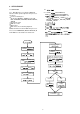
9. ELECTRICAL ADJUSTMENT
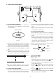
9-1. DVD JITTER ADJUSTMENT
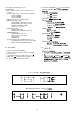
1. Stick the provided small round sticker (0.1 mm thickness)
at the innermost position of a DVD disc as shown and make
a swayed DVD disc.
Fig. 9-2
2. Play back the swayed DVD disc and press the F.F button
repeatedly until the pickup block reaches the outermost
position of its movable range. Next, press the PAUSE button.
3. Set the oscilloscope to the DC input mode and connect it to
the TP201 (HOT) and the TP102 (D.GND) on the MAIN
PCB.
4. Adjust the a screw and b screw alternately so that the AC
and DC level of the waveform is minimum. (DC level should
be less than 1.8 V, AC component should be minimum.)
Fig. 9-3
NOTE: If the SPINDLE MOTOR is replaced, this jitter
adjustment should be performed for proper performance.
9-2. SLICE LEVEL ADJUSTMENT
1. Play back an ordinary DVD disc (single side, one layer) and
press the F.F button repeatedly until the pickup block
reaches almost the center position of its movable range.
2. Set the oscilloscope to the DC input mode and connect it to
the TP201 (HOT) and the TP102 (D.GND) on the MAIN
PCB.
3. Adjust the VR202 so that the DC level is minimum. (The DC
level should be less than 1.8 V)
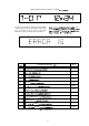
9-3. CD TRACKING BALANCE
1. Set the VR110 at its center position prior to the adjustment.
2. Connect an oscilloscope to the TP150 (TE) on the MAIN
PCB.
3. Play back an ordinary CD-disc and then set it to the PAUSE
mode. If the play mode does not be engage, turn the VR110
at ±15 degrees. If the play mode does still not be engage
even when the VR110 is turned at ±15 degrees, turn the
VR110 at ± 30 degrees and try it again.
4. Observe the waveform and adjust it so that the level A of
the waveform is the same as level B.
Fig. 9-4
Fig. 9-1
TP107
TP105
P800
TP300
VR120
VR121
TP120
VR110
VR202
P807
TP201
P804 P803
JITTER ADJ
SCREW B
JITTER ADJ
SCREW A
Signal recorded side
STICKER
Less than 1.8V
minimum
A
B
500mV
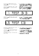
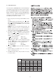
9-4. AS ADJUSTMENT
Adjustment point : VR120
Test point : TP120
1. Turn ON the mains power while depress the “ ” (STOP)
and “ II ” (PAUSE) buttons together. (TEST MODE)
2. Connect the multi meter to test point TP120. Set the multi
meter in DC voltage mode.
3. Press the “ ” (STOP) button several times till the FLD
shows “ LD TEST CD ”. Measure the voltage at that
status.
4. Press the “ ” (STOP) button several times till the FLD
shows “ LD TEST DVD ”.
5. Adjust the voltage at that status 50mV lower than “ LD TEST
CD ” status by the trim resister VR120.