R Model PD4292D User Guide Plasma Monitor PD4292D-1 1 00.10.
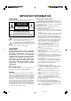
IMPORTANT INFORMATION PRECAUTIONS Please read this manual carefully before using your marantz 42 inch Plasma Monitor and keep the manual handy for future reference. CAUTION RISK OF ELECTRIC SHOCK DO NOT OPEN CAUTION: TO REDUCE THE RISK OF ELECTRIC SHOCK, DO NOT REMOVE COVER (OR BACK) NO USER-SERVICEABLE PARTS INSIDE REFER SERVICING TO QUALIFIED SERVICE PERSONNEL This symbol warms the user that uninsulated voltage within the unit may have sufficient magnitude to cause electric shock.
Recommendations to avoid or minimize phosphor burn-in Like all phosphor-based display devices and all other gas plasma displays, SLIM SERIES PLASMA MONITOR can be susceptible to phosphor burn under certain circumstances. Certain operating conditions, such as the continuous display of a static image over a prolonged period of time, can result in phosphor burn if proper precautions are not taken.
PDP Monitor burning characteristics Regarding the subject titled, we hereby furnish you with the following report: 1. Burning The fluorescent substance used in the plasma module loses its brightness with the lapse of lighting time. This deterioration in brightness appears to be a difference in brightness in relation to the surroundings, and comes to be recognized as burning.
NOTE: When you connect a computer to this monitor, attach the supplied ferrite cores. If you do not do this, this monitor will not comform to mandatory FCC standards. Attaching the ferrite cores. Set the ferrite cores on the both ends of the DVI cable (not supplied), and the one end of the power cable (supplied). Close the lid tightly until the clamps click. Use the band to secure the ferrite core (supplied).
Contents How to Attach Options to the SLIM SERIES 42-inch Plasma Monitor .. 1 Introduction ..................................................... 2 Introduction to the PlasmaSync 42-inch Plasma Monitor ....................................................... 2 The features you'll enjoy include: .............................. 2 Contents of the Package ........................................... 2 Part Names and Function ................................. 3 Front View ...........................................
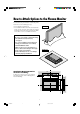
How to Attach Options to the Plasma Monitor You can attach your optional mounts or stand to the plasma monitor in one of the following two ways: Drawing A * As it is upright. (See Drawing A) * As it is laid down with the screen face down (See Drawing B). Lay the protective sheet, which was wrapped around the monitor when it was packaged, beneath the screen surface so as not to scratch the screen face. • This device cannot be installed on its own. Be sure to use a stand or original mounting unit.
Introduction Introduction to the SLIM SERIES PLASMA MONITOR Contents of the Package M PD4292D plasma monitor PD4292D is a seamless blend of cutting-edge visual technology and sophisticated design. At 42-inches, with a 16:9 aspect ratio, the PD4292D certainly makes a big impression. However, at a mere 3.5 inches/ 89mm thin, the monitor's sleek techno-art lines blend in well with your environment.
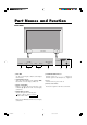
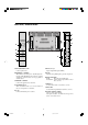
Part Names and Function Front View POWER/STANDBY INPUT SELECT PROCEED VOLUME VOLUME DOWN UP LEFT/– 2 1 INPUT SELECT /EXIT RIGHT/+ POWER/STANDBY 5 4 3 7 1 PROCEED Sets the on-screen display (OSM) mode and displays the main menu. 5 POWER/STANDBY indicator When the power is on ............................. Lights green. When the power is in the standby mode ... Lights red. 2 VOLUME Down and Up Adjust the volume. Functions as the CURSOR (▲/▼) buttons in the On-screen display (OSM) mode.
Rear View/ Terminal Board RGB 3 (Digital RGB) F RGB 3 (Digital RGB) RGB 1 RGB 1 RGB2/ DVD2/ HD2 R/CR/PR LEFT RIGHT R VIDEO 1 VIDEO 2 CONTROL LOCK ON/ OFF VIDEO 3 L(MONO) R CB/CR AC IN G/Y B/CB/PB R VD EXTERNAL CONTROL L(MONO) R VIDEO 1 REMOTE CONTROL VIDEO 2 CONTROL LOCK ON/ OFF VIDEO 3 K R CB/PB AC IN I L(MONO) Y E J AUDIO 3 CR/PR L(MONO) R A EXT SPEAKER L and R Connect speakers here. F RGB3 (DVI 29pin) Inputs a digital RGB signal (TMDS).
LCD REMOTE CONTROLLER RC2000MKII • The remote control unit provided with the Plasma monitor is a “learning”-type, programmable unit capable of controlling almost any component in your system, as well as the Marantz D-BUS components (RC-5). The components to be controlled can be selected with ten buttons. L 4 POWER SOURCE ON 5 L E A R N I N G REMOTE CONTROL MACRO OPERATION The provided remote control unit (RC2000MKII) is a system remote controller.
3 CLONE The RC2000MKII has the ability to “replicate” itself, downloading all of its internal pre-programmed and userprogrammed commands to another RC2000MKII. This button is used when you wish to “teach” another RC2000MKII all of the customized commands you’ve already programmed in this RC2000MKII. 9 FUNCTION Press one of these buttons once or twice to select a particular source component. For example, to set the amplifier or receiver to the laser disc input, press the LD button twice within 2 seconds.
RC2000MKII keypad and DIRECT function commands will be configured for DSS (digital satellite system) control. We have included DSS commands within the RC2000MKII’s pre-programmed memory for RCA brand DSS equipment. If you have another brand of DSS, you can “teach” the RC2000MKII with the remote control codes of your equipment. F CURSOR buttons Some components feature menus that are navigated with up, down, left and right direction commands.
g LEARN indicator: Visible when the RC2000MKII is set to LEARN mode. Liquid Crystal Display (LCD) Window Within this display, all operating messages (function name, mode names, etc.) are shown. When a particular button is pressed (such as a transport command, like PLAY), its status will be shown in the display for 1 minutes. The display will continue to show the source function selected continuously, however.
5. RC2000MKII Basic Operation USE Mode: As supplied from the factory, the RC2000MKII is already permanently programmed with many pre-set commands common to Marantz and Philips equipment, as well as other brands of components that utilize the Philips RC-5 remote control language. 1. If the RC2000MKII is in another mode (LEARN, etc.), press the operation mode button 1 with the tip of a paper clip, until the USE indication appears. 2. Press one of the function buttons 9, such as LD (refer to Figure 1).
5. Press and hold the corresponding SIDE-A button on the laser disc player’s remote transmitter until the “OK” indicator appears in the RC2000MKII LCD window or beep sounds emit. The RC2000MKII changes to the RENAME mode automatically as next step. A function name of the DIRECT function button is blinked, you can rename this blinking function name. You input the desired letter or number with the ten keypad. (See the table in step 3 of the next procedure to referece.
Erasing the memory assigned to a DIRECT buttons: All codes and names which were previously memorized for each of the functions (such as TV, LD, VCR, etc.) in pages can be erased. Press and hold the CLEAR button D and press the < or > button 8 2 times. You will see the “DIR- CLR?” (direct button - clear?) indication in the LCD window (see Figure 5).
3. 4. Press the command buttons in the desired sequence. When you press a command button to be learned into the macro sequence, its name will appear within the LCD window. Every time you press another remote command, the macro step number increases one by one. It is possible during macro programming to adjust the timing of the interval between several macro steps.
4. Using the macro function(s) you have programmed: 1. Press the desired MACRO 6 button. The corresponding macro number will appear at the bottom of the display window, OR if a macro has been programmed under a function button, press the MACRO 6 button twice and hold that function button for 3 seconds.
5. To “clone” (duplicate) the memory contents of one RC2000MKII into another RC2000MKII, please follow these steps: 1. Place the source RC2000MKII (the one with all of the customized commands, names, macros, macro sequences, and the like) with its infrared transmitter window L facing the infrared sensor M of another “fresh” RC2000MKII (5 cm, or 2 inches apart). 2. Press the CLONE button 3 of the source RC2000MKII with the tip of a paper clip, and select “CLONE TX” (clone transmit) mode (see Figure 20).
LAMP - Lighting function ON or OFF and TIME Press the D-5 direct function button, and you can then set the time (in seconds) directly using the numeric key pad B buttons. A time figure consisting of only 1 digit can be input by pressing the figure then waiting for 2 seconds or input “0” before entering a desired digit. You can set time in the range from 0 up to 60 seconds (which would use up more battery life than a lower figure, such as 3 or 5 seconds). “2” is set when shipped from the factory.
TUNER 2 REC 3 PAUS 4 STOP 5 TP-2 6 REC 7 PAUS 8 STOP 2 RDS (for REST only) CD 1 MODE pause stop commands for Tape 2 control (NO output) record pause stop 1 STM 2 AF 3 PTY 4 DISP 5 6 7 8 DWR selects station mode selects AF function selects PTY function selects display function 1 CD+ 2 CD 3 FTS 4 RNDM 5 TRAY 6 TIME 7 REPT 8 AMS CD changer next disc CD changer previous disc favorite track selection random (shuffle) play function tray open/close time display elapsed/remain/total repeat function automat
LD TV 3 REC 6 REC 7 PAUS 8 STOP record pause stop 4 VCD (for REST only) 1 PBC 2 KARA 3 IDX+ 4 IDX5 SEL 6 RTN 7 NEXT 8 PREV selects play back control selects karaoke index up index down play or select audio stop or select return track next track previous 1 RGB 2 VIDEO 3 4 5 DVD 6 7 8 select RGB/PC selects VIDEO 1 ZOM+ 2 ZOM3 4 5 WIDE 6 7 8 enlarge the picture reduce the picture 1 ON 2 3 4 5 OFF 6 7 TIME 8 display the main menu 1 INPUT 2 MODE 3 MENU 4 POINTER VCR 1 MODE 2 PLAY MODE VCR 3
AUX 3 VCD/PHI 2 (for REST only) 5 2 9 6 3 CH 1 8 C 4 0 7 M OK VOL OSD GUIDE MUTE VOL LD remote control unit RC2000MKII OK 18 LD remote control unit Side View Side View RC2000MKII 2 inch 5 cm 18 PD4292D-2 CH 3 command MD (no output) REC-pause pause stop command tape (no output) record pause stop 2 1 MD 2 RECP 3 PAUS 4 STOP 5 TAPE 6 REC 7 PAUS 8 STOP 1 3 REC OSD GUIDE MUTE selects edit mode selects character mode selects delete selects enter selects auto marker syncro REC s
Battery Installation and Replacement Insert the 4 "AA" batteries, making sure to set them in with the proper polarity. Operating Range * Use the LCD remote controller within a distance of about 7 meters from the front of the monitor's remote control sensor and at a horizontal angle of within 30°.
Installation Personal computer with a digital RGB output Signal cable To Mini D-Sub 15 pin connector on the plasma monitor IBM VGA or Compatibles RGB 3 (Digital RGB) RGB 1 Macintosh or Compatibles (Desk top type) RGB2/ DVD2/ HD2 R/CR/PR G/Y B/CB/PB HD AUDIO 1 VD L(MONO) To video, S-video inputs on the plasma monitor Monitor adapter for Macintosh R VIDEO 1 VIDEO 2 VCR or Laser Disc Player AUDIO 3 DVD1/HD1 AUDIO 2 VIDEO 3 L(MONO) R Y CB/PB CR/PR L(MONO) R Document Camera • • For Y/CB/CR,
Connecting Your PC Or Macintosh Computer Connecting Your Document Camera Connecting your PC or Macintosh computer to your plasma monitor will enable you to display your computer's screen image for an impressive presentation. The plasma monitor supports the signals described on page 58. To connect to a PC, Macintosh or compatible graphics adapter, simply: 1. Turn off the power to your plasma monitor and computer. 2.
External Speaker Connections RGB 3 (Digital RGB) RGB 1 – LEFT R/CR/PR RGB2/ DVD2/ HD2 SPEAKERS MUST HAVE MORE THAN 7WATT RATING IMPEDANCE 6 OHM + LEFT RIGHT G/Y – + B/CB/PB HD VD AUDIO 1 RIGHT EXTERNAL CONTROL L(MONO) R VIDEO 1 VIDEO 2 CONTROL LOCK ON/ OFF VIDEO 3 AUDIO 2 REMOTE CONTROL L(MONO) R Y CB/CR AC IN AUDIO 3 PB/PR External speakers may be connected to the plasma monitor to reproduce sound from VIDEO, DVD or RGB signal sources.
Connecting Your PC Or Macintosh Computer Connecting Your VCR Or Laser Disc Player Use common RCA cables (not provided) to connect your VCR or laser disc player to your Plasma monitor. To make these connections, simply: Connecting your PC or Macintosh computer to your Plasma monitor will enable you to display your computer's screen image for an impressive presentation. The Plasma monitor supports the signals described on page 50. To connect to a PC, Macintosh or compatible graphics adapter, simply: 1.
Pin Assignments and Signal Levels for 15 pin RGB (Analog) 5 4 3 2 1 10 9 8 7 6 15 14 13 12 11 Pin No.
Basic Operations POWER DIGITAL ZOOM To turn the unit ON and OFF: 1. Plug the power cord into an active AC power outlet. Digital zoom specifies the picture position and enlarges the picture. 1. Press the 4-D1(ON) button to display the pointer. ( ) To change the size of the picture: Press the 2-D1(ZOM+) button and enlarge the picture. 2. Press the POWER ON button (on the remote controller) to turn on. The monitor’s POWER/STANDBY indicator will light up(green) when the unit is on.
Canceling the off timer 1. Press the 3-D7(TIME) button twice in a row. OFF TIMER To set the off timer: The off timer can be set to turn the power off after 30, 60, 90 or 120 minutes. 2. The off timer is canceled. OFF TIMER0 1. Press the 3-D7(TIME) button to start the timer at 30 minutes. 2. Press the 3-D7(TIME) button to the desired time. 3. The timer starts when the menu turns off. → 30 → 60 → 90 → 120 → 0 OFF TIMER30 Note: After the power is turned off with the off timer ...
WIDE Operations Watching with a wide screen STADIUM size screen (manual) With this function, you can select one of four screen sizes. When watching videos or digital video discs 1. Press the 2-D5(WIDE) button on the remote controller. 2. Within 3 seconds ... Press the 2-D5(WIDE) button again. The screen size switches as follows: The picture is expanded in the horizontal and vertical directions at different ratios. * Use this for watching normal video programs (4:3) with a wide screen.
Watching computer images with a wide screen Information m Supported resolution • See page 58 for details on the display output of the various VESA signal standards supported by the monitor. • When 852 dot2480 line wide VGA (*) signals with a vertical frequency of 60 Hz and horizontal frequency of 31.72 kHz are input, select "WIDE" for the "RGB SELECT" setting. Since selecting an 8482480 signal automatically displays the image in correct size, it is not necessary to change the RGB SELECT setting.
OSM(On Screen Menu) Controls Menu Operations 5. The change is stored until you adjust it again. The OSM window is displayed with respect to the screen as shown on the diagram. 6. Repeat steps 2 – 5 to adjust an additional item, or press the EXIT button on the remote controller to return to the main menu. * Depending on the screen's mode, the OSM may be displayed slightly differently. In the explanation, the OSM section is shown close up. Note: The main menu disappears by pressing the 3D5(OFF) button.
Main menu PICTURE Sub menu CONTRAST BRIGHTNESS SHARPNESS COLOR TINT PICTURE MODE COLOR TEMP NR Functions Adjusts the contrast. Adjusts the brightness. Adjusts the sharpness. Adjusts the color. Adjusts the tint. Sets the picture mode according to the VIDEO environment and image software. Adjusts the color temperature and white balance. Reduces noise visible in image. Main menu SOUND Sub menu BASS TREBLE BALANCE Functions Sets the bass. Sets the treble. Sets the left/right balance.
Picture Settings Menu 4. Press the 3-D1(ON) button. The contrast adjustment is completed. Adjusting the picture The contrast, brightness, sharpness, color and tint can be adjusted as desired. PICTURE CONTRAST BRIGHTNESS SHARPNESS COLOR TINT PICTURE MODE COLOR TEMP. NR Example: Adjusting the contrast Press the 3-D1(ON) button on the remote controller to display the MAIN MENU on the screen, then... 1. Use the ▲ and ▼ buttons to select “PICTURE”, then press the 3-D1(ON) button.
4. Press the 3-D1(ON) button. The picture mode is set to “THEATER”. Setting the picture mode according to the brightness of the room There are four picture modes that can be used effectively according to the environment in which you are viewing the display. PICTURE CONTRAST BRIGHTNESS SHARPNESS COLOR TINT R PICTURE MODE : THEATER COLOR TEMP. : 2 NR : NR-2 Example: Setting the “THEATER” mode Press the 3-D1(ON) button on the remote controller to display the MAIN MENU on the screen, then... 1.
Setting the color temperature Use this procedure to set color tone produced by the plasma display. 5. Once the setting is completed... Press the “OK” button to return to the main menu. To delete the main menu, press the “OK” button once more. Example: Setting "1" Information Press the 3-D1(ON) button on the remote controller to display the MAIN MENU on the screen, then... m Setting the color temperature 1 ......................... High (bluer) 2 ......................... Middle (Standard) 3 ...........
4. Press the 3-D1(ON) button. The "WHITE BALANCE" screen appears. Adjusting the color to the desired quality Use this procedure to adjust the white balance for bright pictures and dark pictures to achieve the desired color quality. 5. Use the ▲ and ▼ buttons to select "RED-GAIN". Example: Adjusting the "WHITE BALANCE" WHITE BALANCE GAIN RED GREEN BLUE BIAS RED GREEN BLUE Press the 3-D1(ON) button on the remote controller to display the MAIN MENU on the screen, then... 1.
4. Press the 3-D1(ON) button. The noise reduction mode is set to “NR-3”. Reducing noise in the picture Use these settings if the picture has noise due to poor reception or when playing video tapes on which the picture quality is poor. PICTURE CONTRAST BRIGHTNESS SHARPNESS COLOR TINT PICTURE MODE COLOR TEMP. NR Example: Setting “NR-3” Press the 3-D1(ON) button on the remote controller to display the MAIN MENU on the screen, then... 1.
Sound Settings Menu To continue adjusting the sound ... Repeat from step 2. Adjusting the treble, bass and left/right balance The treble, bass and left/right balance can be adjusted to suit your tastes. 4. Press the 3-D1(ON) button. The bass has now been adjusted. SOUND Example: Adjusting the bass BASS TREBLE BALANCE Press the 3-D1(ON) button on the remote controller to display the MAIN MENU on the screen, then... 1. Use the ▲ and ▼ buttons to select “SOUND”, then press the 3-D1(ON) button.
Screen Settings Menu 4. Adjust using the § and © buttons. Adjusting the Position, Size, Fine Picture, Picture Adj The position of the image can be adjusted and flickering of the image can be corrected. Example: Adjusting the vertical position in the normal mode Press the 3-D1(ON) button on the remote controller to display the MAIN MENU on the screen, then... V–POSITION 1. Use the ▲ and ▼ buttons to select “SCREEN”, then press the 3-D1(ON) button. The “SCREEN” menu appears.
Information Function Settings Menu m Adjusting the Auto Picture ON ...................... The Picture ADJ and Fine Picture adjustments are made automatically. OFF .................... The Picture ADJ and Fine Picture adjustments are made manually. Setting the on-screen display When using the monitor for presentations, etc., the monitor can be set so that the input source, screen mode, etc., do not appear. m Adjusting the position of the image V-POSITION .......
Adjusting the position of the menu display Use these operations to adjust the position of the menus that appear on screen. 3. To adjust the position... Adjust using the § and © buttons. FUNCTION : : : : : : OSM OSM ADJ. POWER MGT GRAY LEVEL PLE+INVERSE CINEMA MODE RESET Example: Adjusting the position of the menu display Press the 3-D1(ON) button on the remote controller to display the MAIN MENU on the screen, then... 1. Use the ▲ and ▼ buttons to select “FUNCTION”, then press the 3-D1(ON) button.
Setting the power management for computer images This energy-saving (power management) function automatically reduces the monitor’s power consumption if no operation is performed for a certain amount of time. Information m Power management function * The power management function automatically reduces the monitor’s power consumption if the computer’s keyboard or mouse is not operated for a certain amount of time.
POWER/STANDBY indicator Power management mode POWER/STANDBY indicator Power management operating status Description On Green Not activated. Horizontal and vertical synchronizing signals are present from the computer. Picture already on. Standby Orange Activated. No horizontal synchronizing signals are sent from the computer. Operate the keyboard or mouse. The picture reappears immediately. Suspend Red Activated. No vertical synchronizing signals are sent from the computer.
Setting the gray level for the sides of the screen Use this procedure to set the gray level for the parts on the screen on which nothing is displayed when the screen is set to the 4:3 size. Setting the brightness level to the minimum Locking this mode allows you to dim the picture. Example: Adjusting the "GRAY LEVEL" Press the 3-D1(ON) button on the remote controller to display the MAIN MENU on the screen, then...
Setting the picture to suit the movie The film image is automatically discriminated and projected in an image mode suited to the picture. [NTSC, PAL60, 480I (60Hz) only] Resetting to the default values Use these operations to restore all the picture adjustments, audio settings, to the factory default values. Refer to page 17 for items to be reset. Example: Setting the “CINEMA MODE” to “ON” Press the 3-D1(ON) button on the remote controller to display the MAIN MENU on the screen, then...
Option Setting Menu Setting the BNC connectors Select whether to set the input of the 5 BNC connectors to RGB or component. Setting the allocation of the audio connectors Setting the AUDIO 1, 2, and 3 connectors to the desired input. Example: Set the BNC SELECT mode to “COMP.” Example: Set AUDIO 1 to RGB 2. Press the 3-D1(ON) button button on the remote controller to display the MAIN MENU on the screen, then...
Setting a computer image to the correct RGB select screen On the computer image select the RGB mode, moving image (video) mode, wide mode or digital broadcast. Information m RGB SELECT modes One of these 4 modes must be selected in order to display the following signals correctly. Example: Setting the RGB SELECT mode to “VIDEO” RGB ......... VESA 6402480@60Hz (Use this mode for normal computer images.) VIDEO ...... To display the video signal that is converted to the RGB signal, set this mode. WIDE .....
Setting high definition images to the suitable screen size Use this procedure to set whether the number of vertical lines of the input high definition image is 1035 or 1080. Adjusting the display position in the RGB3 input mode If the image is not stable when in the RGB3 input mode, switch the “RGB3 ADJ.” number to 2 or 3. Example: Setting the “1” mode to “2” Example: Setting the "1080B" mode to "1035I" Press the 3-D1(ON) button on the remote controller to display the MAIN MENU on the screen, then...
Information Menu Setting the language for the menus The menu display can be set to one of seven languages: Japanese, English, German, French, Swedish, Italian or Spanish. Checking the frequencies and polarities of input signals Use this function to check the frequencies and polarities of the signals currently being inputted from a computer, etc. Example: Setting the menu display to “DEUTSCH” Press the 3-D1(ON) button on the remote controller to display the MAIN MENU on the screen, then...
Setting the video signal format Use these operations to set the video signal format. 4. Once the setting is completed ... Press the “OK” button to return to the main menu. To delete the main menu, press the “OK” button once more. Example: Setting the video signal format to “3.58 NTSC” The color system is set to “3.58 NTSC”. Press the 3-D1(ON) button on the remote controller to display the MAIN MENU on the screen, then...
External Control Application Communication Parameters These specifications cover the communications control of the plasma monitor by external equipment. (1) (2) (3) (4) (5) (6) (7) Connections Connections are made as described below. External equipment e.g., Personal computer plasma monitor Communication system Interface Baud rate Data length Parity Stop bit Communication code 1) Connector on the plasma monitor side: EXTERNAL CONTROL connector. Type of connector: D-Sub 9-pin male No.
Communication Format 8 bit 8 bit 8 bit 8 bit 8 bit 8 bit Check Sum Example ○ ○ DFH 80H 60H Command 1 Unit ID 1 Unit ID 2 8 bit 8 bit 47H 01H Command 2 Data Length 01H Data 08H Check Sum ▲ Command 1 Total Unit ID 1 208H Unit ID 2 Command 2 2) Error Processing Data length • When the communication interval is vacant for more than 4 ms, thereafter a received Command 1 will be recognized. If, at this time, meaningful data cannot be recognized, that data will not be recognized (as valid data).
Command Reference List 01. 02. 03. 04. 05. 06. 07. 08. 09. 10. 11. 12. 13. 14. 15. 16. 17. 18. 19. 20. 21. 22. 23. 24.
06. AUDIO Mute On 09. COLOR Gain Data Function The external control equipment switches on AUDIO Mute of the plasma monitor. Transmission Data 9FH 80H 60H 3EH 00H CKS Function The external control equipment changes the COLOR gain data of the plasma monitor. Transmission Data DFH 80H 60H 7FH 03H DATA00 DATA01 DATA02 CKS ACK 3FH DATA00: USER PICTURE Gain Flag DATA01: COLOR Gain Flag DATA02: COLOR Gain 60H 80H 3EH 00H CKS 01H 04H EAH: -22 07.
11. SHARPNESS Gain Data ACK 7FH Function The external control equipment changes the SHARPNESS gain data of the plasma monitor.
17. RED Gain Data 19. BLUE Gain Data Function The external control equipment changes the RED Gain Data of the plasma monitor. Transmission Data DFH 80H 60H 7FH 04H DATA00 to DATA03 CKS Function The external control equipment changes the BLUE Gain Data of the plasma monitor.
20. VIDEO ADJ Request DATA05: SHARPNESS Gain Function The display returns the video adjustments information by the external control equipment’s request.
21. Audio Select Set 23. PLE_INVERSE Set Function The external control equipment sets combinations of audio and video inputs for the plasma monitor. Transmission Data DFH 80H 60H 70H 02H DATA00 DATA01 CKS Function The external control equipment sets the PLE and INVERSE (inverse of image brightness) of the plasma monitor.
Table for Signals Supported Supported resolution • When screen mode is NORMAL, each signal is converted to a 640 dots2480 lines signal. (Except for *3) • When screen mode is FULL, each signal is converted to a 853 dots2480 lines signal. (Except for *2) Computer input signals supported on this system Dots 2 lines Model 6402400 6402480 59.9 31.5 YES YES 72.8 37.9 YES YES 75.0 37.5 YES YES 85.0 43.3 YES YES 100.0 51.1 YES YES 120.0 61.3 YES YES 8482480* 60.0 31.
Troubleshooting If the picture quality is poor or there is some other problem, check the adjustments, operations, etc., before requesting service. Symptom Checks Remedy Picture is disturbed. Sound is noisy. Remote control unit operates erroneously. The remote controller does not work. • Is a connected component set directly in front or at the side of the display? • Leave some space between the display and the connected components.
Specifications SLIM SERLES PLASMA MONITOR PD4292D 36.3"(H)220.4"(V) inches 921(H)2518.4(V) mm diagonal 42" 16 : 9 853(H)2480(V) pixels 0.04"(H)20.04"(V) inches 1.08(H)21.08(V) mm 256 levels, 16,770,000 colors Color Reproduction Signals Synchronization Range Horizontal : 15.5 to 80.5 kHz (automatic : step scan) Vertical : 50.0 to 120 Hz (automatic : step scan) Input Signals RGB, NTSC (3.58/4.
R Limited Warranty for the Marantz SLIM SERIES PLASMA MONITOR Who is covered? and brown outs, damages that occur during shipping or transit, or damage which is attributed to acts of God. You must have proof of purchase to receive warranty service. 10) Incidental or consequential damages resulting from the product. (Some states do not allow the exclusion of incidental or consequential damages, so the above exclusion may not apply to you.
is a registered trademark. Printed in Japan PD4292D-2 00/09 MIT 314W851210 61 61 00.10.