R Model PD5020D User Guide Plasma Monitor
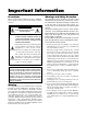
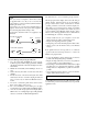
Important Information Precautions Warnings and Safety Precaution Please read this manual carefully before using your Marantz plasma monitor and keep the manual handy for future reference. The Marantz plasma monitor is designed and manufactured to provide long, trouble-free service. No maintenance other than cleaning is required. Use a soft dry cloth to clean the panel. Never use solvents such as alcohol or thinner to clean the panel surface.
NOTE: When you connect a computer to this monitor, attach the supplied ferrite cores. If you do not do this, this monitor will not conform to mandatory FCC standards. Attaching the ferrite cores: Set the ferrite cores on both ends of the DVI cable (not supplied), and both ends of the power cable (supplied). Close the lid tightly until the clamps click. Use the band to fasten the ferrite core (supplied) to the DVI cable.
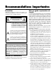
Recommandations importantes Précautions Veuillez lire ce manuel avec attention avant d’utiliser votre moniteur Plasma Marantz et conserver ce manuel à portée de la main pour une consultation ultérieure. ATTENTION RISQUE D’ELECTROCUTION NE PAS OUVRIR MISE EN GARDE: AFIN DE REDUIRE LES RISQUES D’ELECTROCUTION, NE PAS DEPOSER LE COUVERCLE, IL N’Y A AUCUNE PIECE UTILISABLE A L’INTERIEUR DE CET APPAREIL. NE CONFIER LES TRAVAUX D’ENTRETIEN QU’A UN PERSONNEL QUALIFIE.
REMARQUE: Lorsque vous branchez un micro-ordinateur sur ce moniteur, fixez les noyaux en ferrites fournis. Si vous ne le faîtes, le moniteur ne sera pas en conformité avec les exigences des standards FCC. Fixation des noyaux en ferrite. Monter les tores en ferrite aux deux extrêmités du câble DVI (non fourni) et aux deux extrêmités du câble d’alimentation électrique (fourni). Fermez doucement le couvercle jusqu’à ce que les crans se clipsent.
R Limited Warranty for the Marantz SLIM SERIES PLASMA MONITOR Who is covered? You must have proof of purchase to receive warranty service. What is covered? 1) Warranty coverage begins the day you purchase your Plasma Television, and continues for a period of one year. 2) Marantz America will provide in-home warranty repair. 3) Marantz America will incur all labor charges for repairs during the warranty period.
Contents How to Attach Options to the Plasma Monitor .... 1 Introduction ..................................................... 2 Introduction to the Plasma Monitor PD5020D .............. The features you’ll enjoy include: ............................... Contents of the Package ........................................... Options .................................................................. 2 2 2 2 Part Names and Function .................................. 3 Front View .................................
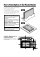
How to Attach Options to the Plasma Monitor You can attach your optional mounts or stand to the plasma monitor in one of the following two ways: Drawing A * While it is upright. (See Drawing A) * As it is laid down with the screen face down (See Drawing B). Lay the protective sheet, which was wrapped around the monitor when it was packaged, beneath the screen surface so as not to scratch the screen face. • This device cannot be installed on its own. Be sure to use a stand or original mounting unit.
Introduction Introduction to the Plasma Monitor PD5020D * You can select RGB source or Component source for the 5BNC terminal. When selecting an RGB input, the source is switched to the RGB input (3); when selecting a component input, the source is switched to the DVD/ HD input (2). Marantz’s Plasma Monitor is a seamless blend of cuttingedge visual technology and sophisticated design. At 50inches, with a 16:9 aspect ratio, the Plasma Monitor PD5020D certainly makes a big impression. However, at a mere 4.
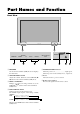
Part Names and Function Front View R POWER/STANDBY INPUT SELECT PROCEED VOLUME VOLUME DOWN UP LEFT/– INPUT SELECT /EXIT RIGHT/+ POWER/STANDBY q PROCEED Sets the On-Screen Menu (OSM) mode and displays the main menu. t POWER/STANDBY indicator When the power is on ............................. Lights green. When the power is in the standby mode ... Lights red. w VOLUME DOWN and UP Adjusts the volume. Functions as the CURSOR (▲/ ▼) buttons in the On-Screen Menu (OSM) mode.
Rear View/ Terminal Board VIDEO 1 VIDEO 2 B AUDIO 1 VIDEO 3 VIDEO 1 VIDEO 2 L ( MONO ) R Y L ( MONO ) CB / PB CR / PR Y L ( MONO ) R RGB 1 R / CR / PR RGB2 / DVD2 / HD2 DVD1/HD1 DVD1 / HD1 R AUDIO 2 L ( MONO ) AUDIO 2 AUDIO 1 VIDEO 3 G/Y CB / PB C CR / PR R B / CB / PB HD AUDIO 3 VD RGB 1 L ( MONO ) R D RGB 3 ( D i g i t a l RGB ) R / CR / PR RIGHT RGB2/DVD2/HD2 CONTROL LOCK ON / OFF SPEAKERS MUST HAVE MORE THAN 7WATT RATING IMPEDANCE 6 OHM REMOTE CONTROL LEFT EXTE
Remote Control w RGB/PC Press this button to select RGB/PC as the source. The available sources depend on the setting of “BNC SELECT”. RGB: → RGB/PC1 → RGB/PC2 → RGB/PC3 COMP.: → RGB/PC1 → RGB/PC3 RGB/PC can also be selected using the INPUT SELECT button on the monitor. e DVD / HD Press this button to select DVD/HD as the source. The available sources depend on the setting of “BNC SELECT”. RGB: HD/DVD/DTV1 COMP.
!3 DISPLAY Displays the source settings on the screen. Battery Installation and Replacement Insert the 2 “AAA” batteries, making sure to set them in with the proper polarity. !4 OFF TIMER Activates the off timer for the unit. 1.Press and open the cover. !5 MULTI Press this button to select a screen mode from among single mode, side by side, and picture in picture. !6 SELECT Press this button to select the active picture in a multi screen mode.
Operating Range * Use the remote control within a distance of about 7 m/ 23ft. from the front of the monitor’s remote control sensor and at horizontal and vertical angles of up to approximately 30°. * The remote control operation may not function if the monitor’s remote control sensor is exposed to direct sunlight or strong artificial light, or if there is an obstacle between the sensor and the remote control. R POWER/STANDBY LUME UP LEFT/– RIGHT/+ INPUT SELECT /EXIT Approx.
Installation VCR or Laser Disc Player To video inputs on the plasma monitor VIDEO 1 VIDEO 2 Document Camera L ( MONO ) DVD1/ HD1 R Y AUDIO 2 AUDIO 1 VIDEO 3 L ( MONO ) CB / PB IBM VGA or Compatibles CR / PR R RGB 1 Macintosh or Compatibles (Desk top type) RGB2 /DVD2 /HD2 R / CR / PR G/Y B / CB / PB HD Monitor adapter for Macintosh AUDIO 3 VD L ( MONO ) R Signal cable To Mini D-Sub 15 pin connector on the plasma monitor RGB 3 ( D i g i t a l RGB ) CONTROL LOCK ON / OFF An image may
Connecting Your PC or Macintosh Computer Connecting Your Document Camera Connecting your PC or Macintosh computer to your plasma monitor will enable you to display your computer’s screen image for an impressive presentation. The plasma monitor supports the signals described on page 55. To connect a PC, Macintosh or compatible graphics adapter, simply: You can connect your plasma monitor to a document camera. To do so, simply: 1. Turn off the power to your plasma monitor and document camera. 2.
External Speaker Connections VIDEO 1 VIDEO 2 LEFT R DVD1 / HD1 RIGHT L ( MONO ) Y AUDIO 2 AUDIO 1 VIDEO 3 L ( MONO ) CB / PB CR / PR R RGB 1 RGB2 / DVD2 / HD2 R / CR / PR G/Y B / CB / PB HD AUDIO 3 VD L ( MONO ) R RGB 3 ( D i g i t a l RGB ) CONTROL LOCK ON / OFF SPEAKERS MUST HAVE MORE THAN 7WATT RATING IMPEDANCE 6 OHM RIGHT LEFT REMOTE CONTROL EXTERNAL CONTROL AC-IN External speakers may be connected to the plasma monitor to reproduce sound from VIDEO, DVD or RGB signal source
Pin Assignments and Signal Levels for 15 pin RGB (Analog) 5 4 3 2 Pin No.
Basic Operations POWER DIGITAL ZOOM To turn the unit ON and OFF: Digital zoom specifies the picture position and enlarges the picture. 1. Plug the power cord into an active AC power outlet. 1. Press the POINTER button to display the pointer. ( 2. Press the POWER ON button (on the remote control) to turn on the unit. ) To change the size of the picture: Press the ZOOM+ button and enlarge the picture. The pointer will change to resemble a magnifying glass.
OFF TIMER To cancel the off timer: To set the off timer: The off timer can be set to turn the power off after 30, 60, 90 or 120 minutes. 1. Press the OFF TIMER button twice in a row. 2. The off timer is canceled. 1. Press the OFF TIMER button to start the timer at 30 minutes. OFF TIMER 0 2. Press the OFF TIMER button to the desired time. 3. The timer starts when the menu turns off. → 30 → 60 → 90 → 120 → 0 OFF TIMER 30 Note: After the power is turned off with the off timer ...
WIDE Operations Watching with a wide screen (manual) STADIUM size screen With this function, you can select one of four screen sizes. When watching videos or digital video discs 1. Press the WIDE button on the remote control. 2. Within 3 seconds ... Press the WIDE button again. The picture is expanded in the horizontal and vertical directions at different ratios. * Use this for watching normal video programs (4:3) with a wide screen.
Watching computer images with a wide screen FULL size screen Switch to the wide screen mode to expand the 4 : 3 image to fill the entire screen. 1. Press the WIDE button on the remote control. 2. Within 3 seconds ... Press the WIDE button again. The screen size switches as follows: The image is expanded in the horizontal and vertical direction. → NORMAL → FULL When wide signals are input. NORMAL size screen (4:3 or SXGA 5:4) TRUE The picture has the same size as the normal computer image.
MULTI SCREEN Operations Showing a couple of pictures on the screen at the same time Operations in the Side-by-side mode To change the picture size, press the cursor or button. * An RGB-input picture may not be displayed in these modes, depending on the input signal specifications. VIDEO1 B A 1. Press the MULTI button to select a screen mode from among single mode, side by side, and picture in picture.
Operations in the Picture-in-picture mode Selecting the input signals to be displayed To move the position of the sub screen, press the cursor or button. 1. Press the SELECT button to make the desired picture active. VIDEO1 B A 2. Press the RGB/PC, VIDEO, or DVD/HD button. Each press of the button changes the selection of the input signal. The INPUT SELECT button on the monitor can also be used to change the selection. RGB/PC1 button VIDEO1 Adjusting the OSM controls button 1.
OSM(On Screen Menu) Controls Menu Operations 5. The adjustment or the setting which you stored is remained. The change is stored until you change it again. The OSM window is displayed with respect to the screen as shown on the diagram. 6. Repeat steps 2 – 5 to adjust an additional item, or press the EXIT button on the remote control to return to the main menu. * Depending on the screen’s mode, the OSM may be displayed differently. In the explanation, the OSM section is shown close up.
Main menu Sub menu Functions PICTURE CONTRAST BRIGHTNESS SHARPNESS COLOR TINT PICTURE MODE COLOR TEMP NR Adjusts the contrast. Adjusts the brightness. Adjusts the sharpness. Adjusts the color. Adjusts the tint. Sets the picture mode according to the VIDEO environment and image software. Adjusts the color temperature and white balance. Reduces noise visible in image.
Picture Settings Menu 4. Once the adjustment is completed ... Press the EXIT button to return to the main menu. Adjusting the picture The contrast, brightness, sharpness, color and tint can be adjusted as desired. To delete the main menu, press the EXIT button once more. Note: If “CAN NOT ADJUST” appears ... When trying to enter the PICTURE submenu, make sure PICTURE MODE is set to MEMORY.
Setting the picture mode according to the brightness of the room There are four picture modes that can be used effectively according to the environment in which you are viewing the display. 4. Once the adjustment is completed ... Press the EXIT button to return to the main menu. To delete the main menu, press the EXIT button once more. Information Example: Setting the “THEATER” mode Types of picture modes MEMORY ........ The last picture adjustments are stored here. THEATER ........
Setting the color temperature Use this procedure to set color tone produced by the plasma display. 4. Once the setting is completed... Press the EXIT button to return to the main menu. To delete the main menu, press the EXIT button once more. Example: Setting “1” Press the PROCEED button on the remote control to display the MAIN MENU on the screen, then... Information Setting the color temperature 1 ...................... High (bluer) 2 ......................... Middle (Standard) 3 ....................
Adjusting the color to the desired quality Use this procedure to adjust the white balance for bright pictures and dark pictures to achieve the desired color quality. 4. Press the PROCEED button. The “WHITE BALANCE” screen appears. 5. Use the ▲ and ▼ buttons to select “RED-GAIN”. WHITE BALANCE GAIN Example: Adjusting the “WHITE BALANCE” RED GREEN Press the PROCEED button on the remote control to display the MAIN MENU on the screen, then... BLUE BIAS RED GREEN 1.
Reducing noise in the picture Use these settings if the picture has noise due to poor reception or when playing video tapes on which the picture quality is poor. 4. Once the setting is completed ... Press the EXIT button to return to the main menu. To delete the main menu, press the EXIT button once more. Example: Setting “NR-3” Information NR * “NR” stands for Noise Reduction. * This function reduces noise in the picture.
Sound Settings Menu To continue adjusting the sound ... Repeat from step 2. Adjusting the treble, bass and left/right balance The treble, bass and left/right balance can be adjusted to suit your tastes. 4. Once the adjustment is completed ... Press the EXIT button to return to the main menu. To delete the main menu, press the EXIT button once more. Example: Adjusting the bass Note : If “CAN NOT ADJUST” appears... Set “AUDIO INPUT” on the OPTION menu correctly.
3. Adjust using the 䊴 and 䊳 buttons. Screen Settings Menu Adjusting the Position, Size, Fine Picture, Picture Adj The position of the image can be adjusted and flickering of the image can be corrected. Example: Adjusting the vertical position in the normal mode Press the PROCEED button on the remote control to display the MAIN MENU on the screen, then... V–POSITION * If neither the 䊴 or 䊳 button is pressed within 5 seconds, the current setting is set and the previous screen reappears. 1.
Function Settings Menu Information Setting the on-screen menu When using the monitor for presentations, etc., the monitor can be set so that the input source, screen mode, etc., do not appear. 䡵 Adjusting the Auto Picture ON ................... The Picture ADJ and Fine Picture adjustments are made automatically. OFF ................. The Picture ADJ and Fine Picture adjustments are made manually. Example: Turning the on-screen menu mode off 䡵 Adjusting the position of the image V-POSITION ...
Adjusting the position of the menu display Use these operations to adjust the position of the menus that appear on the screen. 3. To adjust the position... Adjust using the 䊴 and 䊳 buttons. OSM Example: Adjusting the position of the menu display Press the PROCEED button on the remote control to display the MAIN MENU on the screen, then... FUNCTION : ON OSM ADJ. : 2 POWER MGT : OFF GRAY LEVEL : 3 CINEMA MODE : ON RGB3 ADJ. : 1 LONG LIFE 1.
Setting the power management for computer images This energy-saving (power management) function automatically reduces the monitor’s power consumption if no operation is performed for a certain amount of time. Information 䡵 Power management function * The power management function automatically reduces the monitor’s power consumption if the computer’s keyboard or mouse is not operated for a certain amount of time.
POWER/STANDBY indicator Power management POWER/STANDBY Power management mode indicator operating status Description Turning the picture back on On Green Not activated. Horizontal and vertical synchronizing signals are present from the computer. Picture already on. Standby Orange Activated. No horizontal synchronizing signals are sent from the computer. Operate the keyboard or mouse. The picture reappears immediately. No vertical synchronizing signals are sent from the computer.
Setting the picture to suit the movie The film image is automatically discriminated and projected in an image mode suited to the picture. [NTSC, PAL, PAL60, 480I (60Hz), 525I (60Hz), 576I (50Hz), 625I (50Hz), 1035I (60Hz), 1080I (60Hz) only] Setting the gray level for the sides of the screen Use this procedure to set the gray level for the parts on the screen on which nothing is displayed when the screen is set to the 4:3 size.
Setting RGB3 ADJ. When the picture input from the RGB3 input terminal is distorted, select the most appropriate setting from among “1”, “2”, and “3”. Reducing burn-in of the screen The brightness of the screen, the position of the picture, positive/negative mode and screen wiper are adjusted to reduce burn-in of the screen. Example: Setting “2” Example: Setting “PLE” to “LOCK” Press the PROCEED button on the remote control to display MAIN MENU on the screen, then...
Setting the time for “INVERSE” Set the “INVERSE” or “WHITE” display time and the “WAITING TIME”. 5. Once the setting is completed... Press the EXIT button to return to the FUNCTION menu. To exit the main menu, press the EXIT button twice. Example: Setting so that the INVERSE mode starts in 30 minutes and proceeds for one and a half hours. Information Perform Steps 1-2 on Page 32, then 䡵 PLE AUTO .............. The brightness of the screen is adjusted automatically to suit the picture quality. LOCK ....
Setting the time for “SCREEN WIPER” Set the “SCREEN WIPER” operation time, “WAITING TIME”, and “SPEED”. The 2nd line of the “WORKING TIME”: → 0M ↔ 3M ↔ 6M ↔ 9M ↔ ... ↔ 57M ← The 1st line of the “WAITING TIME”: Example: Setting so that the SCREEN WIPER mode starts in 30 minutes and proceeds for one and a half hours. → 0H ↔1H ↔ 2H ↔ 3H ↔ ... ↔ 12H ← The 2nd line of the “WAITING TIME”: → 0M ↔ 3M ↔ 6M ↔ 9M ↔ ... ↔ 57M ← Perform Steps 1-2 on Page 32, then: 6. Once the setting is completed...
Resetting to the default values Use these operations to restore all the picture adjustments, audio settings, to the factory default values. Refer to page 19 for items to be reset. The 2nd line of the “WORKING TIME”: → 0M ↔ 3M ↔ 6M ↔ 9M ↔ ... ↔ 57M← The 1st line of the “WAITING TIME”: → 0H ↔1H ↔ 2H ↔ 3H ↔ ... ↔ 12H← Press the PROCEED button on the remote control to display the MAIN MENU on the screen, then... The 2nd line of the “WAITING TIME”: → 0M ↔ 3M ↔ 6M ↔ 9M ↔ ... ↔ 57M← 1.
Options Settings Menu Setting the BNC connectors Select whether to set the input of the 5 BNC connectors to RGB or component. Setting the allocation of the audio connectors Setting the AUDIO 1, 2, and 3 connectors to the desired input. Example: Set the BNC SELECT mode to “COMP.” Example: Setting “AUDIO 1” to “VIDEO 2” Press the PROCEED button on the remote control to display the MAIN MENU on the screen, then... Press the PROCEED button on the remote control to display the MAIN MENU on the screen, then.
Setting a computer image to the correct RGB select screen With the computer image, select the RGB Select mode for a moving image such as (video) mode, wide mode or digital broadcast. Information 䡵 RGB SELECT modes One of these 6 modes must be selected in order to display the following signals correctly. AUTO .............. Select the suitable mode for the specifications of input signals as listed in the table “Computer input signals supported by this system” on page 55. STILL ..............
Setting high definition images to the suitable screen size Use this procedure to set whether the number of vertical lines of the input high definition image is 1035 or 1080. Setting the picture size for RGB input signals Use this procedure to switch the setting to “ON” or “OFF”. Example: Setting the “ON” mode to “OFF” Example: Setting the “1080B” mode to “1035I” Press the PROCEED button on the remote control to display the MAIN MENU on the screen, then...
Information Menu Setting the language for the menus The menu display can be set to one of seven languages: Japanese, English, German, French, Swedish, Italian or Spanish. Checking the frequencies, polarities of input signals, and resolution Use this function to check the frequencies and polarities of the signals currently being input from a computer, etc. Example: Setting the menu display to “DEUTSCH” Press the PROCEED button on the remote control to display the MAIN MENU on the screen, then...
Setting the video signal format Use these operations to set the color systems of composite video signals or Y/C input signals. 4. Once the setting is completed ... Press the EXIT button to return to the main menu. To delete the main menu, press the EXIT button once more. Example: Setting the color system to “3.58 NTSC” The color system is set to “3.58 NTSC”. Press the PROCEED button on the remote control to display the MAIN MENU on the screen, then...
External Control Application Communication Format These specifications cover the communications control of the plasma monitor by external equipment. 8 bit 8 bit 8 bit 8 bit 8 bit 8 bit Command 1 Connections Unit ID 1 Connections are made as described below. Unit ID 2 External equipment e.g., Personal computer plasma monitor 8 bit 8 bit Command 2 Data length Data Check sum 1) Connector on the plasma monitor side: EXTERNAL CONTROL connector. Type of connector: D-Sub 9-pin male No.
Command Reference List 01. Power ON 02. Power OFF 03. Input Switch Change 04. VOLUME Gain Data 05. AUDIO Mute On 06. AUDIO Mute Off 07. CONTRAST Gain Data 08. BRIGHT Gain Data 09. SHARPNESS Gain Data 10. Color Gain Data 11. TINT Gain Data 12. PICTURE MODE Select 13. COLOR TEMP SELECT 14. RED Gain Data 15. GREEN Gain Data 16. BLUE Gain Data 17. NR MODE Set 18. BASS Gain Data 19. TREBLE Gain Data 20. BALANCE Gain Data 21. SCREEN MODE Select 22. V. POSITION Gain Data 23. H. POSITION Gain Data 24.
ACK 04. VOLUME Gain Data Function The external control equipment changes the VOLUME gain data of the plasma monitor. 7FH 60H 7FH 03H DATA00 DATA01 DATA02 CKS DATA00: USER SOUND Gain Flag 05H DATA01: VOLUME Gain Flag 01H DATA02: VOLUME Gain 00H: Step 0 80H 7FH 02H DATA00 DATA01 CKS DATA00: USER PICTURE Gain Flag DATA01: CONTRAST Gain Flag Transmission Data DFH 80H 60H 01H 07H 08. BRIGHT Gain Data Function The external control equipment changes the BRIGHT gain data of the plasma monitor.
10. COLOR Gain Data 13. COLOR TEMP SELECT Function The external control equipment changes the COLOR gain data of the plasma monitor. Function The external control equipment changes the COLOR TEMP of the plasma monitor. Transmission Data Transmission Data DFH 80H 60H 7FH 03H DATA00 DATA01 DATA02 CKS DATA00: USER PICTURE Gain Flag DATA01: COLOR Gain Flag DATA02: COLOR Gain * COLOR Gain is from -22 (EAH) to +22 (16H) only during video.
15. GREEN Gain Data 17. NR MODE Set Function The external control equipment changes the GREEN Gain Data of the plasma monitor. Note that this command can be accepted only when PRO is selected from COLOR TEMP. Transmission Data Function The external control equipment sets the NR (Noise Reduction) mode of the plasma monitor.
20. BALANCE Gain Data 23. H. POSITION Gain Data Function The external control equipment changes the BALANCE gain data of the plasma monitor. Transmission Data Function The external control equipment changes the H. POSITION gain data of the plasma monitor.
26. AUTO PICTURE Select 28. CLOCK Gain Data Function The external control equipment switches on or off the AUTO PICTURE of the plasma monitor. Transmission Data Function The external control equipment changes the CLOCK gain data (ratio of frequency division) of the plasma monitor.
30. OSM ADJ. Gain Data 33. CINEMA MODE Set Function The external control equipment sets the position of the OSM menu of the plasma monitor. Transmission Data Function The external control equipment switches on or off the CINEMA MODE of the plasma monitor. Transmission Data DFH 80H 60H 1AH 02H DATA00: OSM ADJ. Gain Flag DATA01: 01H: 1 DATA00 DATA01 CKS DFH 80H 02H 60H C1H 01H DATA00 CKS DATA00: CINEMA MODE Set 01H: ON 02H: OFF ACK 09H: 9 7FH ACK 7FH 60H 80H 1AH 01H DATA00: OSM ADJ.
36. INVERSE Set 38. RESET Function The external control equipment sets the INVERSE (inverse of image brightness) and the WHITE of the plasma monitor. Function The external control equipment resets the user adjustment of the plasma monitor.
40. BNC SELECT 43. PICTURE SIZE Select Function The external control equipment sets the BNC SELECT of the plasma monitor. Function The external control equipment sets the PICTURE SIZE SELECT of the plasma monitor.
ACK The display returns the following ACK. 45. COLOR SYSTEM Select Function The external control equipment sets the COLOR SYSTEM of the plasma monitor. Transmission Data DFH 80H 60H 5CH 01H 7FH 60H 80H 5CH 01H DATA00 CKS DATA00: 01H: 3.58NTSC 02H: 4.43NTSC 03H: PAL 04H: SECAM 0AH: AUTO1 0BH: PAL60 0CH: AUTO2 0DH: PAL- M 0EH: PAL- N Function The external control equipment selects single screen mode or multi screen mode of the display.
47. FREQUENCY Request Function The external control equipment inquires the Horizontal frequency, Vertical frequency, Horizontal sync polarity, Vertical sync polarity, Mode, and Resolution of the plasma monitor.
49. VIDEO ADJ Request DATA05: SHARPNESS Gain Function The display returns the video adjustments information by the external control equipment’s request.
50. Audio Select Request 52. MODEL NAME Request Function The external control equipment inquires the current combinations of audio and video inputs for the plasma monitor. Transmission Data Function The external control equipment inquires the product code of the plasma monitor.
Table of Signals Supported Supported resolution • When the screen mode is NORMAL, each signal is converted to a 1024 dots⳯768 lines signal. (Except for *2, 3, 4) • When the screen mode is TRUE, the picture is displayed in the original resolution. • When the screen mode is FULL, each signal is converted to a 1365 dots⳯768 lines signal. (Except for *3) Computer input signals supported by this system Model Vertical frequency (Hz) 70.1 59.9 72.8 75.0 85.0 100.4 120.4 60.0 60.0 56.3 60.3 72.2 75.0 85.1 99.
*1 Only when using a graphic accelerator board that is capable of displaying 852⳯480. *2 This signal is converted to a 1024 dots ⳯ 640 lines signal. *3 The picture is displayed in the original resolution. *4 The aspect ratio is 5:4. This signal is converted to a 960 dots⳯768 lines signal. *5 Normally the RGB select mode suite for the input signals is set automatically. If the picture is not displayed properly, set the RGB mode prepared for the input signals listed in the table above.
Troubleshooting If the picture quality is poor or there is some other problem, check the adjustments, operations, etc., before requesting service. Symptom Checks Picture is disturbed. • Is a connected component set directly in Sound is noisy. front or at the side of the display? Remote control operates erroneously. The remote control does not work.
Specifications Color Reproduction Signals Synchronization Range Input Signals Input Terminals RGB Visual 1 (Analog) Visual 2 (Analog) Visual 3 (Digital) Video Visual 1 Visual 2 Visual 3 DVD/HD/DTV Visual 1 Visual 2 Audio External Control Sound output Power Supply Current Rating Power Consumption Dimensions 1.89" (48) 48.8" (1240) 43.5" (1106) Horizontal : 15.5 to 93.8 kHz (automatic : step scan) Vertical : 50.0 to 120 Hz (automatic : step scan) RGB, NTSC (3.58/4.
COUNTRY ALGERIE ARMENIA AUSTRALIA AUSTRIA BAHREIN BANGLADESH BELGIUM BULGARIA CANADA CHINA CYPRUS CZECH REPUBLIC DENMARK DUBAI EGYPT ESTONIA F.Y.R.O.M. FINLAND FRANCE GERMANY GREECE HEADQUARTERS EUROPE: HONG KONG HUNGARY ICELAND INDIA IRAN IRELAND ISRAEL ITALY IVORY COAST JAPAN KOREA KUWAIT LATVIA LEBANON LITHUANIA MALAYSIA MALTA MAURITIUS MILITARY MARKET EUROPE NETHERLANDS NEW ZEALAND NORWAY OMAN POLAND PORTUGAL PROFESSIONAL EUROPE PROFESSIONAL U.S.A.