Model PM-11S1 User Guide Integrated Amplifier
ENGLISH ITALIANO WARRANTY For warranty information, contact your local Marantz distributor. RETAIN YOUR PURCHASE RECEIPT Your purchase receipt is your permanent record of a valuable purchase. It should be kept in a safe place to be referred to as necessary for insurance purposes or when corresponding with Marantz. IMPORTANT When seeking warranty service, it is the responsibility of the consumer to establish proof and date of purchase. Your purchase receipt or invoice is adequate for such proof. FOR U.K.
CE MARKING English The PM-11S1 is in conformity with the EMC directive and low-voltage directive. Français Le PM-11S1 est conforme à la directive EMC et à la directive sur les basses tensions. Deutsch Das Modell PM-11S1 entspricht den EMC-Richtlinien und den Richtlinien für Niederspannungsgeräte. Nederlands De PM-11S1 voldoet aan de EMC eisen en de vereisten voor laag-voltage. Español El PM-11S1 está de acuerdo con las normas EMC y las relacionadas con baja tensión.
Español Svenska ADVERTENCIAS - No exponga el equipo a la lluvia ni a la humedad. - No extraiga la tapa del equipo. - No introduzca nada en el interior del equipo a través de los orificios de ventilación. - No maneje el cable de alimentación con las manos mojadas. - No cubra la ventilación con objetos como manteles, periódicos, cortinas, etc. - No deben colocarse sobre el equipo elementos con fuego, por ejemplo velas encendidas.
2 3 4 5 ABOUT THE BALANCED INPUT JACKS ........................................................................................................... 5 WIRING SPEAKER CABLE ................................................................................................................................ 5 BI-WIRING CONNECTION ................................................................................................................................. 6 COMPLETE BI-AMP CONNECTION ..............................
ENGLISH ENGLISH FOREWORD This section must be read before any connection is made to the mains supply. 7 EQUIPMENT MAINS WORKING SETTING Your Marantz product has been prepared to comply with the household power and safety requirements that exist in your area. PM-11S1 can be powered by 230V AC only. 7 COPYRIGHT Recording and playback of any material may require consent.
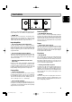
INTEGRARED AMPLIFIER PM-11S1 DISPLAY ATT. TONE PRE OUT OPERATE SPEAKER A REC OUT INPUT SELECTOR VOLUME POWER ON/OFF SPEAKER B PHONES The PM-11S1 is an integrated amplifier developed on the concepts of Marantz’s SC-7S1 and MA-9S1 flagship amplifiers. • HDAM SA2 The HDAMSA2 is an evolved version of the HDAMSA incorporated into the SC-7S1 and MA-9S1. It drives the phono amplifier, balance buffer, line buffer, volume amplifier, voltage amplifier and power buffer that comprise the PM-11S1.
ENGLISH ENGLISH BEFORE USE 7 Do Not Locate in the Following Places To ensure long-lasting use, do not locate the PM-11S1 where: • Exposed to direct sunlight. • Near to sources of heat such as heaters. • Highly humid or poorly ventilated. • Dusty. • Subjected to mechanical vibrations. • On wobbly, inclined or otherwise unstable surfaces • Radiated heat is blocked such as in cramped audio racks. To ensure proper heat radiation, ensure the below clearance from walls and other equipment.
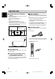
q The PM-11S1 uses XLR connectors for the BALANCED INPUT jacks. XLR connectors are widely used with professional equipment because of the following features. • Incoming music signals are balanced, therefore they are little affected by external noise. • The detachable locking mechanism minimizes connector play and enhances connection reliability. WIRING SPEAKER CABLE • Be careful not to short circuit in wiring speaker cables. • Peel off the corting of speaker cable as shown below. Approx.
ENGLISH ENGLISH BEFORE MAKING CONNECTIONS Here following are explained two types of connections that improve sound quality. The speakers in these explanations have low and mid/high input jacks that support a bi-amp connection. To determine whether or not your speakers support a biamp connection, check in the instruction manual that came with your speakers or contact the manufacturer.
CONNECTIONS Connection Example 1: Basic Connection for Normal Stereo Playback Refer also to the instruction manuals of components to connect equipment correctly. • Use a bi-wiring connection for speakers. Set the SPEAKER A and B buttons on the front panel in the ON position. • If using speakers that do not support a bi-wiring connection, connect them to either the SPEAKER SYSTEM A or B terminals. • If using an active subwoofer, set the PRE OUT button on the front panel in the ON position.
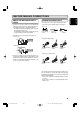
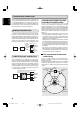
CONNECTIONS Connection Example 2: Basic Connection for 5.1 Multi-Channel Playback Using 3 PM-11S1 The three PM-11S1s are connected by FCBS. For the FCBS connection, prepare 3 portable audio connection cables with monaural ⇔ monaural miniplugs or stereo ⇔ stereo miniplugs as described “ABOUT FCBS” on pg. 17. Set the ID numbers for the PM-11S1 units as explained “HOW TO SET ID” on pg. 21. When the PM-11S1 of ID 1 is operated, those of ID 2 and ID 3 will operate in sync.
SUPER AUDIO CD PLAYER SA-11S1 OPEN/ CLOSE PLAY STOP DISPLAY OFF POWER ON/OFF SOUND MODE Set SPEAKER A button on front panel in ON position. PAUSE Set to “BI-AMP”. Set PM-11S1 for L CH to ID 1. 3 2 AC IN 3 1 2 Set SPEAKER A button on front panel in ON position. 1 Set to “BI-AMP”. Set PM-11S1 for R CH to ID 2. 3 2 AC IN 3 1 2 1 To power outlet To power outlet MF / HF MF / HF LF LF Remove L CH speaker shorting bar. Remove shorting bar. Remove R CH speaker shorting bar.
ENGLISH ENGLISH NAMES AND FUNCTIONS OF PARTS FRONT PANEL INTEGRARED AMPLIFIER PM-11S1 DISPLAY ATT. TONE PRE OUT OPERATE SPEAKER A REC OUT INPUT SELECTOR VOLUME POWER ON/OFF SPEAKER B PHONES q POWER ON/OFF Switch This switch turns power to the PM-11S1 ON and OFF. When pressed, power is activated and the blue indicator on the display w lights up. Approximately 8 seconds after power is activated, audio output is enabled. Pressing the switch again turns power OFF.
This button turns output from the PRE OUT jack on the rear panel ON and OFF. When output is ON, the center of the button is lit a blue color. !2 REC OUT Button This button turns the signals output from the RECORDER 1 and 2 OUT jacks on the rear panel ON and OFF. When output is ON, the center of the button is lit a blue color. For instructions on how to record, see “RECORDING” on pg. 16. When RECORDER 1 is selected as the input source, signals are not output to the RECORDER 1 OUT jack.
ENGLISH ENGLISH NAMES AND FUNCTIONS OF PARTS REAR PANEL 3 2 AC IN 3 1 2 1 A PHONO GND Terminal Connect the grounding wire from an analog record player here. B PHONO Input Jacks These jacks are for connecting to an analog record player. Both MC and MM cartridges can be used, therefore set the PHONO MC button on the front panel according to the type of cartridge you are using. In the bi-amp mode, the R channel jack cannot be used.
This remote controller can control the PM-11S1 and Marantz Super Audio CD players and DVD players that have a remote control receptor. The operations possible by remote control may differ with each component, therefore see the instruction manual that came with the component. Remote controller buttons are laid out as shown below. z Input Selector Buttons These buttons are for selecting the input source to use in playback. x TRIM Button This button starts trimming.
ENGLISH ENGLISH NAMES AND FUNCTIONS OF PARTS The buttons in groups , and . are for operating Marantz products other than the PM-11S1, such as Super Audio CD players and DVD players. The function of each button changes to match the component selected as the input source from the input selector buttons z. When the CD and BALANCED buttons are pressed, the buttons in groups , and . function as indicated in the below table.
To explain how to play back input sources, representative examples are given with an Super Audio CD player and analog record player. Before starting either procedure, check the component is correctly connected to the PM-11S1. 7 Disc Playback on an Super Audio CD Player 1. Press the power ON/OFF switch of the Super Audio CD player to activate power to it. 7. 8. PM-11S1 or the VOLUME 3/4 buttons n of the remote controller.
ENGLISH ENGLISH BASIC OPERATION RECORDING INTEGRARED AMPLIFIER PM-11S1 This example explains how to record from an input source such as an Super Audio CD player to a recording device such as a CD-R. DISPLAY ATT. TONE PRE OUT OPERATE SPEAKER A REC OUT INPUT SELECTOR 1. Press the power ON/OFF switch of the Super Audio CD VOLUME POWER ON/OFF PHONES SPEAKER B PHONO MC player and CD-R to activate power to both components. 2. Press the POWER ON/OFF switch q of the PM-11S1 to 3. 4. 5. 6. 7.
FCBS is short for Floating Control Bus System. It is a communication system that connects up to four PM-11S1s over a dedicated bus line so as to enable synchronized operations amongst them via 2-way data communications. The FCBS connections can be made with either of the below two types of portable audio connection cable. Prepare the number of connection cables for the number of PM-11S1s to connect.
ENGLISH ENGLISH HOW TO USE AND SET FEATURES 2. Set the attenuation level. The setting changes with each ATTENUATION (ATT) press of the ATT button on the PM-11S1. Attenuation is a one-touch feature for reducing volume level. When the ATT button on either the PM-11S1 or the remote controller is pressed, the volume level is attenuated. When the PM-11S1 is shipped from the factory, the attenuation level is set to –20 dB, but it can be set to –20 dB, -40 dB or -∞. 1.
There are three trimming modes. • LEVEL trimming that adjusts the volume level on left and right channels • BASS trimming that adjusts the bass on left and right channels • TREBLE trimming that adjusts the treble on left and right channels The volume level of the left and right channels can be trimmed in 0.5 dB steps across a 0.0 - -9.0 dB range. When the PM11S1 is shipped from the factory, the volume level is set to 0.0 dB (maximum). 1. Press the TRIM button once to access the LEVEL trimming mode.
ENGLISH ENGLISH HOW TO USE AND SET FEATURES 7 How to Trim Bass 7 How to Trim Treble The bass level of the left and right channels can be trimmed in 2 dB steps across a -8.0 - +8.0 dB range. When the PM-11S1 is shipped from the factory, the bass level is set to 0 dB. To trim the bass level, activate tone control by pressing the TONE button on either the PM-11S1 or the remote controller. The treble level of the left and right channels can be trimmed in 2 dB steps across a -8.0 - +8.0 dB range.
An LCD is used as the PM-11S1’s display. You can set the contrast in the +8 - -8 range. When the PM-11S1 is shipped from the factory, the contrast level is set to 0. The contrast adjustment mode is accessed by activating power from the POWER ON/OFF button while pressing and holding the DISPLAY button. Contrast is then set by turning the INPUT SELECTOR knob to the desired setting. HOW TO SET ID If using the PM-11S1 by itself as a stereo amplifier, set the ID to “0”.
ENGLISH ENGLISH TROUBLESHOOTING If you experience trouble with the PM-11S1, make the below checks before thinking the worst. Improper operation can cause the PM-11S1 to behave in a way that makes you think something is wrong with the equipment when actually not. If the trouble cannot be fixed after making the below checks, contact the place of purchase, your nearest Marantz dealer, our customer service center or our repair service center. 7 About Protective Circuits * Power does not turn ON.
7 Error Messages When multiple PM-11S1s are connected by FCBS, the below error messages may appear on the display. In these cases, there is a problem with the ID number setting or remote cable connection. Check the ID numbers and remote cable as indicated in the below table. For details on how to set ID numbers, see “How to Set ID” on pg. 21. Error message Meaning What to do 1 ERROR 02 ID 2 is used with more than one amp. 2 ERROR 03 ID 3 is used with more than one amp.
Power output (20 Hz – 20 kHz simultaneous drive of both channels) .................................................... 100W x 2 (8Ω load) .................................................... 200W x 2 (4Ω load) Total frequency distortion (20Hz – 20kHz simultaneous drive of both channels, 8Ω load) .......................................... 0.01% Output band width (8Ω load, 0.05%) .................. 5Hz ~50kHz Frequency response (CD, 1W, 8Ω load) ..... 5Hz ~ 120kHz±3dB Dumping factor (8Ω load, 20Hz – 20kHz) ..
www.marantz.com You can find your nearest authorized distributor or dealer on our website. JAPAN Marantz Japan, Inc. 35-1 Sagami Ohno 7-Chome, Sagamihara-shi, Kanagawa 228-8505, Japan U.S.A. Marantz America, Inc. 1100 Maplewood Drive, Itasca, IL 60143, U.S.A. EUROPE Marantz Europe B.V. P.O. Box 8744, 5605 LS Eindhoven, The Netherlands is a registered trademark.