Model PM-11S2 User Guide Integrated Amplifier
CAUTION RISK OF ELECTRIC SHOCK DO NOT OPEN CAUTION: TO REDUCE THE RISK OF ELECTRIC SHOCK, DO NOT REMOVE COVER (OR BACK) NO USER-SERVICEABLE PARTS INSIDE REFER SERVICING TO QUALIFIED SERVICE PERSONNEL The lightning flash with arrowhead symbol within an equilateral triangle is intended to alert the user to the presence of uninsulated “dangerous voltage” within the product’s enclosure that may be of sufficient magnitude to constitute a risk of electric shock to persons.
IMPORTANT SAFETY INSTRUCTIONS READ BEFORE OPERATING EQUIPMENT This product was designed and manufactured to meet strict quality and safety standards. There are, however, some installation and operation precautions which you should be particularly aware of. 1. Read these instructions. 2. Keep these instructions. 3. Heed all warnings. 4. Follow all instructions. 5. Do not use this apparatus near water. 6. Clean only with dry cloth. 7. Do not block any ventilation openings.
ENGLISH WARRANTY For warranty information, contact your local Marantz distributor. RETAIN YOUR PURCHASE RECEIPT Your purchase receipt is your permanent record of a valuable purchase. It should be kept in a safe place to be referred to as necessary for insurance purposes or when corresponding with Marantz. IMPORTANT When seeking warranty service, it is the responsibility of the consumer to establish proof and date of purchase. Your purchase receipt or invoice is adequate for such proof. FOR U.K.
CE MARKING English The PM-11S2 is in conformity with the EMC directive and low-voltage directive. Français Le PM-11S2 est conforme à la directive EMC et à la directive sur les basses tensions. Deutsch Das Modell PM-11S2 entspricht den EMC-Richtlinien und den Richtlinien für Niederspannungsgeräte. Nederlands De PM-11S2 voldoet aan de EMC eisen en de vereisten voor laag-voltage. Italiano Il PM-11S2 è conforme alle direttive CEE ed a quelle per i bassi voltaggi.
Deutsch - Italiano WARNHINWEISE Das Gerät nicht Regen, Feuchtigkeit, Tropf- oder Spritzwasser aussetzen. Die Abdeckung nicht vom Gerät abnehmen. Keine Gegenstände durch die Belüftungsschlitze stecken. Das Netzkabel nicht mit feuchten oder nassen Händen anfassen. Decken Sie die Lüftungsöffnungen nicht mit einem Tischtuch, einer Zeitung, einem Vorhang usw. ab. Es dürfen keine Gegenstände mit offener Flamme, wie etwa brennende Kerzen, auf dem Gerät aufgestellt werden.
Thank you for selecting the Marantz PM-11S2 Integrated amplifier for your Audio system. Please read these operating instructions carefully. We recommend that you read the entire user guide before you attempt to connect or operate the player. After you have reviewed the contents of this manual, we suggest that you make all system connections before you attempt to operate the unit.
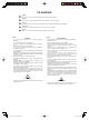
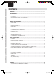
ENGLISH NAMES AND FUNCTIONS CONTENTS FEATURES ..................................................................................................................3 BEFORE USING ..........................................................................................................4 EQUIPMENT MAINS WORKING SETTING.......................................................................................4 COPYRIGHT .................................................................................................
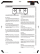
ENGLISH DISPLAY NAMES AND FUNCTIONS FEATURES ATT. TONE PRE OUT OPERATE SPEAKER A REC OUT INPUT SELECTOR VOLUME Input Amplifier Section ¶ Constant Current Feedback Phono Equalizer The Constant Current Feedback Phono Equalizer of the highergrade SC-11S1 model is also provided with this model. This equalizer, developed by Marantz, has the advantages of both NF-type and CR-type phono equalizers, and it supports both MM and MC cartridges.
ENGLISH NAMES AND FUNCTIONS BEFORE USING This section must be read before any connection is made to the mains supply. BASIC CONNECTIONS EQUIPMENT MAINS WORKING SETTING Your Marantz product has been prepared to comply with the household power and safety requirements that exist in your area. — Power requirements (U.S.A.) ....................AC 120V 60Hz — Power requirements (Europe) ..............AC 230V 50/60Hz COPYRIGHT BASIC OPERATIONS Recording and playback of any material may require consent.
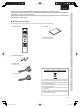
BEFORE USING Operate the unit with the remote controller within the range of the illustration below. BASIC CONNECTIONS Before using the remote controller for the first time, load the batteries in the remote controller. The batteries provided are used to verify the operations of the remote controller only. 1. Remove the battery cover. BASIC OPERATIONS Approx. 5m 2. Insert the batteries with correct +/– orientation. Two AAA-size (R03) batteries Remote controller Precautions 3.
ENGLISH NAMES AND FUNCTIONS NAMES AND FUNCTIONS FRONT PANEL q wer t y ui o BASIC CONNECTIONS DISPLAY ATT. TONE PRE OUT !0 OPERATE SPEAKER A REC OUT INPUT SELECTOR VOLUME POWER ON/OFF SPEAKER B PHONES BASIC OPERATIONS !4 q INPUT SELECTOR Knob ADVANCED CONNECTIONS This knob is for selecting the input source to use in playback and recording. The selected input source is displayed in the display !2. w DISPLAY Button This button turns the display and side illumination ON and OFF.
ENGLISH VOLUME Indicator Volume Display Max !5 Turn the VOLUME knob on the unit to the right, or press the VOLUME 5 button on the remote controller. !6 OPERATE !7 BASIC CONNECTIONS DISPLAY NAMES AND FUNCTIONS NAMES AND FUNCTIONS !6 Display Panel Approximately 3 seconds after the power to the unit is activated, the ID number is displayed here. After that, the top line displays the selected input source, and the bottom line displays the volume level. The volume attenuation (dB units) is displayed.
ENGLISH NAMES AND FUNCTIONS NAMES AND FUNCTIONS REMOTE CONTROLLER BASIC CONNECTIONS This remote controller can be used to control the PM-11S2 and Marantz Super Audio CD players or DVD players that have a remote control receptor. The operations possible by remote control may differ with each component, therefore see the instruction manual that came with the component. OPEN/ CLOSE SOUND MODE z Input Selector Buttons These buttons are for selecting the input source to use in playback.
ENGLISH NAMES AND FUNCTIONS NAMES AND FUNCTIONS REAR PANEL !2 AC IN 3 1 2 1 !1 q LINE 1/2 Input Jacks These jacks are for connecting to the output jacks of a tuner, DVD player, etc. w CD Input Jacks These jacks are for connecting to the output jacks of a Super Audio CD player, etc. e PHONO GND Terminal Connect the grounding wire from an analog record player here. r PHONO Input Jacks These jacks are for connecting to an analog record player.
ENGLISH NAMES AND FUNCTIONS BASIC CONNECTIONS CONNECTING AUDIO COMPONENTS CD player, etc. Record player To BALANCED LINE OUT jack SUPER AUDIO CD PLAYER SA-11S1 OPEN/ CLOSE PLAY BASIC CONNECTIONS STOP DISPLAY OFF SOUND MODE CD Player POWER ON/OFF PAUSE To LINE OUT jack SUPER AUDIO CD PLAYER SA-11S1 OPEN/ CLOSE PLAY BASIC OPERATIONS STOP DISPLAY OFF SOUND MODE POWER ON/OFF PAUSE 3 2 2 1 To LINE OUT jack Tuner, etc. ADVANCED CONNECTIONS DVD Player, etc.
• Insert the plugs of the connections cords firmly into the connecting jacks. Incorrect insertion may cause noise. • Connect the wires correctly to the L (left) and R (right) channels. The red jack is the R (right) channel, and the white jack is the L (left) channel. • Make sure that input and output are connected correctly. • Refer also to the instruction manuals of components to connect equipment correctly.
ENGLISH NAMES AND FUNCTIONS BASIC CONNECTIONS CONNECTING SPEAKER SYSTEMS BASIC CONNECTIONS • If using an active subwoofer, set the PRE OUT button on the front panel to ON. • Your speaker system needs to meet the following requirements. If speakers that do not meet the following requirements are used, the amplifier protective circuit may trip, and sounds will not playback correctly. In certain cases, damage may also be caused to the amplifier and speaker system.
BASIC CONNECTIONS • Peel off the coating of speaker cable as shown below. 1. Plug the supplied AC power cable to the AC IN socket on Peel off the edge of cable. BASIC CONNECTIONS the rear panel of the main unit. Approx. 1 cm Cut the coating of cable. CONNECTING OF AC POWER CABLE Twist conductors. AC IN Insert conductor of cable. Turn clockwise to tighten. • Wiring with “Y” style terminal Turn counterclockwise to loosen. Insert conductor. 2. Plug the power cable into an AC outlet.
ENGLISH NAMES AND FUNCTIONS BASIC OPERATIONS PLAYBACK To explain how to play back input sources, representative examples are given with an Super Audio CD player and analog record player. Before starting either procedure, check the component is correctly connected to the PM-11S2. BASIC CONNECTIONS 7 Disc Playback on an Super Audio CD Player 1. Press the power ON/OFF switch of the Super Audio CD player to activate power to it. 2. Press the POWER ON/OFF switch !3 of the PM-11S2 6.
PHONO BALANCED RECORDER 1 LINE 1 RECORDER 2 TRIM CD LINE 2 EXIT TONE + L R ENTER DISPLAY - ATT Function Open/Closes disc tray. Selects Super Audio CD sound mode. SOUND MODE Selects Super Audio CD/CD. 3 Play Track skip 4 (Returns to track beginning/previous track.) ¢ Track skip (Advances to next track.
ENGLISH NAMES AND FUNCTIONS ADVANCED CONNECTIONS BI-WIRING CONNECTION BASIC CONNECTIONS A bi-wiring connection separately connects the low and mid/high jacks of the speaker to the amplifier using separate speaker cables. Because separate cables are used for low and mid/high sounds, the return current generated in the low speaker causes little interference with the mid/high speaker. • If speakers that do not support bi-wiring connection are used, connect them to either the SPEAKER A or B terminals.
STEREO COMPLETE BI-AMP CONNECTION q The two amplifiers are connected by F.C.B.S. for synchronized use. For F.C.B.S. connection, connect with commercially available monaural ⇔ monaural miniplugs or stereo ⇔ stereo miniplugs as described in F.C.B.S. (page. 20). w Set the ID numbers as explained in HOW TO SET ID NUMBERS (page. 21). When the ID1 amplifier is operated, the ID 2 amplifier will operate in sync. e Connect the analog output of the CD player etc. to the L ch input jacks of both pre-amps.
ENGLISH NAMES AND FUNCTIONS ADVANCED CONNECTIONS SPEAKER POSITIONING FOR SUPER AUDIO MULTI-CHANNEL SOUND BASIC CONNECTIONS BASIC OPERATIONS ADVANCED CONNECTIONS In order to enjoy Super Audio CD multi-channel sound with the best possible acoustics, it is recommended to position speakers as specified in ITU-R BS.775-1 of the International Telecommunication Union (ITU).
BASIC CONNECTION FOR 5.1 MULTI-CHANNEL PLAYBACK q The three units are connected using F.C.B.S. For the F.C.B.S connection, prepare 3 audio connection cables, and refer to F.C.B.S. on page 20. w Set the ID numbers for the three amplifiers as explained in HOW TO SET ID NUMBERS (page. 21). When the ID 1 unit is operated, ID 2 and ID 3 units will operate in sync. e Connect the outputs of players that have 5.1 channel analog outputs to each of the three units.
ENGLISH NAMES AND FUNCTIONS ADVANCED CONNECTIONS F.C.B.S. BASIC CONNECTIONS F.C.B.S. (Floating Control Bus System) is a communication system that connects up to four PM-11S2s over a dedicated bus line so as to enable synchronized operations amongst them via 2-way data communications. Prepare the correct number of portable audio connection cables for the number of units to be connected. Either of the following types of connection cables are adequate.
If using this unit by itself as a stereo amplifier, set the ID number to “0” (Default setting is “0”). Note: If the ID number is set to a number other than “0”, this unit cannot be used for standalone operation. The ID number of the unit appears on the display for about 3 seconds after the power is activated. When multiple PM-11S2s are connected, a unique ID number must be set of each one in order to distinguish between them. The unit that centrally controls the other units takes ID 1.
ENGLISH NAMES AND FUNCTIONS ADVANCED OPERATIONS 7 How to Trim Volume Level TRIMMING BASIC CONNECTIONS There are three trimming modes. • LEVEL trimming that adjusts the volume level on left and right channels • BASS trimming that adjusts the bass on left and right channels • TREBLE trimming that adjusts the treble on left and right channels The volume level of the left and right channels can be trimmed in 0.5dB steps across a 0.0 – 9.0dB range.
1. Press the TRIM button once to access the LEVEL trimming mode. 2. Press the ENTER button once to access the BASS trimming mode. mode. 2. Press the ENTER button twice to access the TREBLE trimming mode. 3. The flashing “0” on the left indicates that trimming is 3. The flashing “0” on the left indicates that trimming is activated for the left channel bass level. Press the 3 and 4 buttons to set the bass level of the left channel. activated for the left channel treble level.
ENGLISH NAMES AND FUNCTIONS ADVANCED OPERATIONS HOW TO OPERATE THE SIDE ILLUMINATION ATT. (ATTENUATION) ATT. button Illumination Lamp DISPLAY button DISPLAY ATT. BASIC CONNECTIONS PRE OUT TONE DISPLAY ATT. OPERATE SPEAKER A REC OUT PRE OUT TONE INPUT SELECTOR VOLUME OPERATE POWER ON/OFF SPEAKER B PHONES PHONO MC SPEAKER A REC OUT INPUT SELECTOR VOLUME POWER ON/OFF SPEAKER B ATT is a one-touch feature for reducing the volume level.
Power is not supplied. The protection circuit is activated. Speaker connection is incomplete. Input cable connection is incomplete. Use of the connected player is wrong. Power is supplied, but no sound is heard from the speakers. Sound is heard from the left or right speakers only. Or, the volume from the right and left speakers differs. Left and r ight channels are reversed. Sound is monaural. Noise occurs during record playing. Or, no sound is heard.
ENGLISH NAMES AND FUNCTIONS TROUBLESHOOTING 7 About the protection circuit BASIC CONNECTIONS This unit is equipped with a protection circuit to protect the amplifier circuits and speaker system from damage. If the protection circuit is activated, the sound is instantly muted. In this case, the message “PROTECT” flashes on the display panel, and the OPERATE indicator also flashes. To deactivate the protection circuit, turn the unit off then back on again after about 1 minute or more.
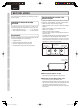
ENGLISH Power output (20 Hz – 20 kHz simultaneous drive of both channels) .....................................................100W x 2 (8Ω load) .....................................................200W x 2 (4Ω load) 15-3/4 (400) 17-1/2 (444) Total frequency distortion (20Hz – 20kHz simultaneous drive of both channels, 8Ω load) ..........................................................................0.01% Output band width (8Ω load, 0.05%) ..................
ENGLISH NAMES AND FUNCTIONS OTHERS BASIC CONNECTIONS BASIC OPERATIONS 7 Cleaning of equipment external surfaces 7 Repairs The exterior finish of your unit will last indefinitely with proper care and cleaning, Never use scouring pads, steel wool, scourging powders or harsh chemical agents (e.g., lye solution), alcohol, thinner, benzine, insecticide or other volatile substances as these will mar the finish of the equipment. Likewise, never use cloths containing chemical substances.
www.marantz.com You can find your nearest authorized distributor or dealer on our website. is a registered trademark. Printed in Japan PM-11S2_UN_00_cover etc.indd 2 08/2008 541110120036M mzh-g 08.8.