R Model PM-14mkII User Guide Integrated Amplifier 69
ENGLISH WARRANTY Condizioni di garanzia For warranty information, contact your local Marantz distributor. RETAIN YOUR PURCHASE RECEIPT Your purchase receipt is your permanent record of a valuable purchase. It should be kept in a safe place to be referred to as necessary for insurance purposes or when corresponding with Marantz. L'apparecchio e' garantito per 365 giorni dalla data di acquisto comprovata da un documento attestante il nominativo del rivenditore e la data di vendita.
CONTENTS LIST ENGLISH English .................................................................................................................................................................................................................... page 3 Français ................................................................................................................................................................................................................ page 10 Deutsch ...........................
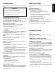
PRECAUTIONS This section must be read before any connection is made to the mains supply. The following precautions should be taken when operating the equipment.
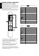
NAME AND FUNCTION OF EACH PART ENGLISH (Figure 1) r Volume Control Knob (VOLUME) A PHONE INPUT jacks This knob adjusts the volume. Turning the knob to the right ( ), increases the volume. The volume can also be turned up or down with the remote control unit. Connect the output jacks of a turntable to these jacks. B CD PLAYER INPUT jacks t Balance Control Knob (BALANCE) Connect the output jacks of a Compact Disc player to these jacks.
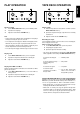
TAPE DECK OPERATION CD CD 21 PHONO LINE 19 25 1 INTEGRATED AMPLIFIER LINE 21 17 PHONO LINE INTEGRATED AMPLIFIER 14 LINE 32 19 25 1 15 29 PM-14mkII 2 17 15 29 PM-14mkII 2 14 32 13 52 4 13 38 38 LINE LINE 3 12 12 3 10 40 10 40 48 48 CD-R TEMP 4 TEMP 66 66 2 BAL. UNBAL. TAPE 7 7 52 CD-R 2 BAL. UNBAL.
ENGLISH REMOTE CONTROL OPERATION (Remote control unit: RC-17mkIIPM) Button functions when the TAPE 1 button (see z of the figure 3) is pressed: The RC-17mkIIPM remote control unit can control MARANTZ audio/ video components equipped with an infrared remote sensor as well as other MARANTZ components which are connected with the above components through the remote control bus. The following illustration shows the button layout of the RC-17mkIIPM.
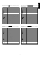
Button Button functions when the LINE 1 (TUNER) button (see z of the figure 3) is pressed: Function Button Function Play Not used. Fast forward Frequency Up Rewind Frequency Down Not used. Not used. Stop Not used. OPEN/CLOSE Open/close OPEN/CLOSE Not used.
PRE OUT, MAIN IN TERMINALS How to use the remote control unit ENGLISH 1. Remote control unit The distance between the signal transmitter of the remote control unit (RC-17mkIIPM) and the IR SENSOR of the integrated amplifier (PM14mkII) should be less than about 5 meters. To ensure remote control, the remote control unit should be pointed accurately toward the IR SENSOR and there should be no obstacle between the remote control unit and the IR SENSOR.
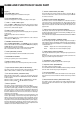
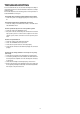
TROUBLESHOOTING ENGLISH In case of trouble with the set, first check the following before calling for service. What seems to be a serious malfunction is often due to a simple operation mistake. If the trouble still persists after checking, please consult your dealer or nearest MARANTZ service agent. The amplifier does not function and the indicator does not light. 1. Check if the power cord is plugged properly into an AC power outlet. The indicator lights but the amplifier will not function. 1.
TECHNICAL SPECIFICATIONS (DIN) Rated power output (20 Hz to 20 kHz, 2CH simultaneous drive) ...................................................................................................... 100 W x 2 (8 Ω load) 160 W x 2 (6 Ω load) 200 W x 2 (4 Ω load) Total harmonic distortion (20 Hz to 20 kHz, 2CH drive, 8 Ω load) .......................................................................................................................... 0.01 % Cross-modulation distortion (SMPTE) .......................
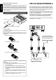
CD UNBALANCED R R L + L R – – REMOTE CONTROL + L LINE 2 GND OUT IN LINE 1 /TUNER CD BALANCED R PUSH L PUSH R LINE 3 IN SELECTOR CD-R CONNECTION OUT MM MC 1 – GND 2 – COLD 3 – HOT R IN TAPE + L R L L MAIN IN PHONO R – – + L SPEAKER SYSTEMS SYSTEM A : 4 – 16 OHMS SYSTEM B : 4 – 16 OHMS S Y S T E M A + B : 8 – 16 OHMS COUPLED OUT R PRE OUT SEPARATE AC INLET CD 21 PHONO LINE 19 25 1 INTEGRATED AMPLIFIER LINE 17 15 29 PM-14mkII 14 32 2 13 38 LINE 3
SPEAKER CONNECTIONS This unit can accept the connection of speakers equipped with dedicated terminals for bi-wire connection. Bi-wire connection is possible by connecting each speaker to both the SYSTEM A and SYSTEM B terminals. Speakers which do not use bi-wire connection or which are not equipped with bi-wire connection terminals can be connected to either SYSTEM A or SYSTEM B terminals. However, in this case, it is recommended to use the SYSTEM A terminals in consideration of sound quality.
COUNTRY ALGERIE ARMENIA AUSTRALIA AUSTRIA BAHREIN BANGLADESH BELGIUM BULGARIA CANADA CHINA CYPRUS CZECH REPUBLIC DENMARK DUBAI EGYPT ESTONIA F.Y.R.O.M. FINLAND FRANCE GERMANY GREECE HEADQUARTERS EUROPE: HONG KONG HUNGARY ICELAND INDIA IRAN IRELAND ISRAEL ITALY IVORY COAST JAPAN KOREA KUWAIT LATVIA LEBANON LITHUANIA MALAYSIA MALTA MAURITIUS MILITARY MARKET EUROPE NETHERLANDS NEW ZEALAND NORWAY OMAN POLAND PORTUGAL PROFESSIONAL EUROPE PROFESSIONAL U.S.A.