Model PM4000 User Guide INTEGRATED AMPLIFIER 1
ABOUT THIS USER GUIDE Refer to the Figures on the pages at the rear of this user guide. The callout numbers on the Figures correspond to those found in the text. All references to the connections and controls that are printed in BOLD type are as they appear on the unit. This section must be read before any connection is made to the mains supply. English WARNINGS PRECAUTIONS Do not expose the equipment to rain or moisture. The following precautions should be taken when operating the equipment.
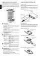
CONTROLS, CONNECTORS, AND INDICATORS English !4 q VOLUME CONTROL Adjusts the volume level. Turn the knob clockwise to increase the volume. PHONO INPUT JACKS Connect the output jacks of a turntable to these jacks. w GND (GROUND) TERMINAL Connect the grounding wire from the turntable to this terminal. !5 BALANCE CONTROL Turn the knob to correct an unbalanced program source such as stereo broadcast or to vary the output level of the left or right channel.
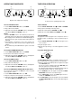
OPERATION PROCEDURES TAPE DECK OPERATION q A w INTEGRATED AMPLIFIER PM4000 INPUT SELECTOR VOLUME English PHONO CD TUNER TONE DEFEAT ON PHONES STANDBY SOURCE CD-RfiTAPE TAPEfiCD-R COPY TAPE VOLUME PHONO LOUDNESS TONE DEFEAT BASS TREBLE ON OFF REC SELECTOR OFF POWER ON/OFF AUX INPUT SELECTOR CD-R/MD MUTE ON OFF MIN 1 SPEAKERS MAX BALANCE POWER ON/OFF PHONES STANDBY CD SOURCE + ON OFF L BASS TREBLE ON OFF MIN SPEAKERS MAX BALANCE 2 AUX – REC SELECTOR Operat
REMOTE CONTROL UNIT RC8000PM USING THE REMOTE CONTROL UNIT z 1. Remote control Operate the remote control unit within a distance of approx. 5 m from the infrared signal reception window (remote sensor) on the front of the Amplifier. Remote control operation may not be possible if the remote control unit's transmitter is not pointing in the direction of the remote sensor or if there is an obstruction between the transmitteote sensor.
TROUBLE SHOOTING This section describes the care and maintenance tasks that must be performed to optimize the operation of your Marantz equipment. In case of trouble or abnormal operation of the unit, check the following before contacting service personnel. What may seem to be a serious malfunction is often the result of a simple operation mistake. If the trouble persists after checking the following, please contact your dealer or nearest Marantz distributor.
MODEL PM4000 TECHNICAL SPECIFICATIONS (DIN) Power output RMS 8 Ohms/4 Ohms (40 Hz – 20 kHz) .................................................................................................................................. 30 / 40 W DIN 8 Ohms / 4 Ohms ............................................................................................................................................................... 35 / 45 W IHF dynamic power 8 Ohms / 4 Ohms ......................................................
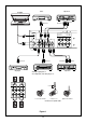
Tuner Turntable Tape deck INPUT OUTPUT OUTPUT GND SPEAKER SYSTEMS SYSTEM 1 : 4 -16 OHMS SYSTEM 2 : 4 -16 OHMS SYSTEM 1+2 : 8 -16 OHMS SYSTEM 2 R PHONO CD TUNER AUX CD-R/MD L TAPE L R IN OUTPUT OUT IN OUT R L SYSTEM 1 OUTPUT OUTPUT INPUT Tape deck CD player Analogur output jacks or AV components, video disc player, etc.
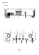
Model PM4000 N Version GND SPEAKER SYST EM S S Y S T EM 1 : 4 -16 OHMS S Y S T EM 2 : 4 -16 OHMS S Y S T EM 1 + 2 : 8 -16 OHMS ∼ SYSTEM 2 R PHONO CD TUNER AUX CD-R/MD REMOTE CONTROL L IN TAPE OUT L R IN OUT IN R OUT y qwe r t u !2 !0 L SYSTEM 1 o i !7 !3 !4 !6 INTEGRATED AMPLIFIER PM4000 INPUT SELECTOR VOLUME PHONO CD TUNER TONE DEFEAT ON PHONES STANDBY SOURCE LOUDNESS ON BASS OFF MIN TREBLE 1 SPEAKERS MAX BALANCE 2 PHONO CD TAPEfiCD-R TUNER COPY AUX –