English Model PM7000 User Guide Français Français Integrated Amplifier 1
CONTENTS Engligh ...................................................................................................................................... page 6 Français Français English Français ..................................................................................................................................
CAUTION RISK OF ELECTRIC SHOCK DO NOT OPEN CAUTION: TO REDUCE THE RISK OF ELECTRIC SHOCK, DO NOT REMOVE COVER (OR BACK) Français The lightning flash with arrowhead symbol, within an equilateral triangle, is intended to alert the user to the presence of uninsulated "dangerous voltage" within the product's enclosure that may be of sufficient magnitude to constitute a risk of electric shock to persons.
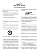
SAFETY INSTRUCTIONS READ BEFORE OPERATING EQUIPMENT This product was designed and manufactured to meet strict quality and safety standards. There are, however, some installation and operation precautions which you should be particularly aware of. 2. Retain Instructions — The safety and operating instructions should be retained for future reference. 3. Heed Warnings — All warnings on the appliance and in the operating instructions should be adhered to. 4.
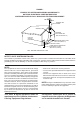
FIGURE 1 EXAMPLE OF ANTENNA GROUNDING ACCORDING TO NATIONAL ELECTRICAL CODE INSTRUCYIONS CONTAINED IN ARTICLE 810 -"RADIO AND TELEVISION EQUIPMENT" English ANTENNA LEAD IN WIRE GROUND CLAMP Français ELECTRIC SERVICE EQUIPMENT GROUNDING CONDUCTORS (NEC SECTION 810-21) GROUND CLAMPS POWER SERVICE GROUNDING ELECTRODE SYSTEM (NEC ART 250, PART H) NEC - NATIONAL ELECTRICAL CODE NOTE TO CATV SYSTEM INSTALLER: This reminder is provided to call the CATV (Cable-TV) system installer's attention to Article 820
ABOUT THIS USER’S GUIDE CONNECTIONS Figure numbers refer to the illustrations located at the back of this User’s Manual. Numbers assigned to parts and controllers match the callout numbers used inside the illustrations. ALL UPPER-CASE BOLD type indicates the name of a connection or controller as it is actually marked on the amplifier. (Figure 1) CONNECTING A TUNER Connect the output jacks of your stereo tuner to the TUNER jacks of this amplifier.
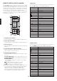
!1 Power Cord CONTROLS, CONNECTORS, AND INDICATORS Connect the power cord to a standard household power outlet. (Figure 2) These terminals can used to connect other audio equipment that is equipped with a remote control bus terminal. Connection requires a special cable. The bus OUT terminal sends signal to the connected equipment, while the bus IN terminals receive signals.
!9 Record (REC) Selector Switch OPERATION Use this switch to select recording between the tape deck and CD-R(MD) or recording of the signal selected by the INPUT SELECTOR SWITCH and output from the REC OUT jacks. See the note under "Tape Deck CD-R(MD) Operation on page 9 for full details about settings.
TAPE DECK CD-R/MD OPERATION A Use the REC SELECTOR E to specify the type of recording you want to perform. 1. The OFF setting cuts off all signal output from the REC OUT jacks. Note that REC SELECTOR E should normally be in the OFF setting except when you are recording to tape. The OFF setting shortens the signal path within the amplifier, which minimizes crosstalk and other factors that can cause deterioration of the sound. 2.
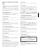
REMOTE CONTROL UNIT RC 8000PM CD BUTTON The following are the functions assigned to control buttons after the CD amplifier source button is pressed. The RC8000PM remote control unit can be used to control any Marantz AV equipment that has a remote sensor, as well as other Marantz equipment connected to the main equipment’s remote control bus. The buttons of the remote control unit are arranged on the control panel according to functional groups as shown in the illustration below.
CD-R BUTTON The following are the functions assigned to control buttons after the CD-R amplifier source button is pressed.
USING THE REMOTE CONTROL UNIT MD BUTTON The following are the functions assigned to control buttons after the MD amplifier source button is pressed.
CARE AND MAINTENANCE TROUBLESHOOTING This section describes care and maintenance that you must perform in order to make sure your Marantz amplifier performs at the level for which it is designed. Be sure to unplug the amplifier from the mains supply before any care and maintenance. Whenever you have a problem with the amplifier, check the following points before requesting service. What may seem to be a serious malfunction is often the result of a simple operational error.
MODEL PM7000 TECHNICAL SPECIFICATIONS Power output RMS 8 ohms (20 Hz-20 kHz) .......................................................................................................................... 95 W DIN 8 ohms .................................................................................................................................................. 105 W THD at 8 ohms RMS rated output ................................................................................................................
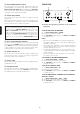
Tape Deck FIGURES Processor Input Output Output Input English Tuner PROCESSOR SPEAKER SYSTEMS IN IN SYSTEM 1 SYSTEM 2 SYSTEM 1AND 2 CD-R/MD : : : MINIMUN 8 MINIMUN 8 MINIMUN 16 OHMS OHMS OHMS OUT OUT SYSTEM 2 L R SYSTEM 1 L Français Français R IN AUX2 TAPE OUT AUX1 TUNER R L CD R L PHONO Output CD player Turntable NOTE: Turn the knobs on the speaker terminals by hand. (Do not use a tool to turn the knobs.
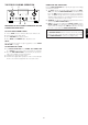
PROCESSOR IN SPEAKER SYSTEM 1 : SYSTEM 2 : SYSTEM 1 AND 2 : IN CD-R/MD OUT OUT + Français w e r – SYSTEM 2 – R L + AC OUTLETS AC 120V 60HZ IN AUX2 TAPE TUNER SWITCHED 1.
ADDRESS 4 Station Street, Thornleigh NSW 2120, Australia Taborstraße 95 / Ladestraße 1, Gebäude Hangartner, A-1200 Wien, Austria Brusselbaan 278, 9320 Erembodegem, Belgium Makedonia Blvd. 16, 1606 Sofia, Bulgaria 633 Granite Court, Pickering, Ontario P.O. Box 5604, Nicosia, Cyprus Fugnerova 1, 67801 Blansko, Czech Republic Aboulevarden 1, DK-8000 Arhus C., Denmark P.O. Box 105, Dubai, U.A.E. Lo Hu 12, EE0026 Tallin, Estonia ul.