R Model SR6300 User Guide AV Surround Receiver
CAUTION RISK OF ELECTRIC SHOCK DO NOT OPEN CAUTION: TO REDUCE THE RISK OF ELECTRIC SHOCK, DO NOT REMOVE COVER (OR BACK) NO USER-SERVICEABLE PARTS INSIDE REFER SERVICING TO QUALIFIED SERVICE PERSONNEL The lightning flash with arrowhead symbol within an equilateral triangle is intended to alert the user to the presence of uninsulated “dangerous voltage” within the product’s enclosure that may be of sufficient magnitude to constitute a risk of electric shock to persons.
IMPORTANT SAFETY INSTRUCTIONS READ BEFORE OPERATING EQUIPMENT This product was designed and manufactured to meet strict quality and safety standards. There are, however, some installation and operation precautions which you should be particularly aware of. 1. Read Instructions – All the safety and operating instructions should be read before the product is operated. 2. Retain Instructions – The safety and operating instructions should be retained for future reference. 3.
20. Servicing – Do not attempt to service this product yourself as opening or removing covers may expose you to dangerous voltage or other hazards. Refer all servicing to qualified service personnel. 21. Damage Requiring Service – Unplug this product from the wall outlet and refer servicing to qualified service personnel under the following conditions: a. When the power-supply cord or plug is damaged. b. If liquid has been spilled, or objects have fallen into the product. c.
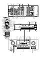
a s d f g h L DIGITAL IN / OUT j k R R L R CD L OUT R L OUT FRONT PRE OUT FRONT MONI TOR TAPE MONITOR TAPE OUT VCR1 VCR1 OUT CDR / MD DSS / VCR2 DSS / VCR2 DIG - 5 IN ANTENNA OUT SURR. L DIG - 4 IN CENTER SURR. CENTER SUB WOOFER SUB WOOFER R CDR / MD AM SPEAKER SYSTEMS B SURROUND DIG - 3 IN VCR1 VCR1 VCR1 VCR1 DSS / VCR2 DSS / VCR2 DSS / VCR2 DSS / VCR2 TV TV TV DVD DVD DVD MODEL NO. SR6300 DIG.OUT COAX GND CENTER SURR.
INTRODUCTION ............................................ 2 REMOTE CONTROLLER OPERATION ..... 24 FEATURES .................................................... 3 CONTROLLING THE SR6300 ............................................................. 24 CONTROLLING MARANTZ COMPONENTS ...................................... 24 LEARN MODE ..................................................................................... 26 MACRO MODE ............................................................................
ENGLISH INTRODUCTION Thank you for purchasing the Marantz SR6300 DTS/Dolby Digital Surround receiver. This remarkable component has been engineered to provide you with many years of home theater enjoyment. Please take a few minutes to read this manual thoroughly before you connect and operate the SR6300. As there are a number of connection and configurations options, you are encouraged to discuss your own particular home theater setup with your Marantz A/V specialist dealer.
6.1 CHANNEL PRE-AMP OUTPUTS 6.1 channel pre-amp outputs for connection to external components such as a subwoofer and external power amplifiers. BUILT-IN 6 CHANNEL POWER AMPLIFIER 6.1CH DIRECT INPUT 100 watts to each of the six main channels ; the power amp section features an advanced, premium high- storage power supply capacitors, and fully discrete output stages housed in cast aluminum heat sinks . 6.1ch direct inputs accommodate future multi-channel sound formats or an external digital decoder.
ENGLISH i S- ( Source) DIRECT button FRONT PANEL FEATURES (SEE PAGE iii.) When this button is pressed, the tone control circuit is bypassed as well as Bass Management. Notes: • The surround mode is automatically switched to AUTO when the source direct function is turned on. • Additionally, Speaker Configurations are fixed automatically as follow.
Connect to the outputs of DVD Audio player, SACD Multi channel player or an external multichannel decoder. ¡0 DIGITAL outputs All connections to the rear panel should be made with the entire system powered off. To avoid errors, it is advisable to connect one cable at a time between the various components. Optical and Coaxial Connect to the digital input of your digital recording equipment. ¡1 DIGITAL inputs a FM antenna terminal (75 ohms) Dig.1,2 (Optical) and Dig.
ENGLISH REMOTE CONTROLER RC7300SR ⁄2 (TV) CH 3/4 buttons NAMES AND FUNCTIONS ⁄3 TOP MENU button z Infrared window (when DVD mode is selected) Used to call up the top menu of the DVD. Used to increase or decrease the TV channel. Outputs and inputs an infrared control signals. ⁄4 Tone / Deck cotrol buttons x LCD (Liquid Crystal Display) Tone cotrol buttons (when AMP mode is selected) The TREBLE buttons are used to adjust the tone control of high frequency sound for left and right speaker.
‹1 A/D button (when AMP mode is selected) Used to exit SETUP MAIN MENU or On Screen Display. This is used to switch between the analog and digital inputs. ‹2 SLEEP (sleep timer) button ¤1 TEST button This button is used for setting the sleep timer. It can be operated the same way as the button in unit. (when AMP mode is selected) Used to enter the test tone menu. ‹3 7.1/6.1CH IN button ¤2 MENU/OSD button Press this button to select the output of an external multi channel decoder.
ENGLISH REMOTE CONTROL RANGE GENERAL INFROMATION OF RC7300SR TO SR6300 The distance between the transmitter of the remote control unit and the IR SENSOR of the SR6300 should be less than about 5 meters. If the transmitter is pointed to a direction other than the IR SENSOR or if there is an obstacle between them, remote control may not be possible. To control the SR6300 by your RC7300SR, you have to select the device AMP by function selector button. Please refer as below for the details in AMP mode.
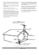
Front left and right speakers, and a center speaker Align the tweeters and mid-range drivers on the three front speakers on the same height as well as possible. SPEAKER PLACEMENT Surround left and right speakers, and surround center speaker Place the surround left, right and surround center speakers higher to your ears 2 Ft. - 3 Ft.(70cm – 1m). Also place the speakers on the same height.
ENGLISH CONNECTING SPEAKERS PASSIVE SUBWOOFER POWERED SUBWOOFER POWER AMPLIFIER INVERT OUTPUT INPUT INPUT LEVEL BTL EXT. CONT. IN FRONT SPEAKER SYSTEMS LEFT RIGHT RIGHT B LEFT REMOTE CONT. MASTER SLAVE MIN MAX VIDEO/ +5~13V DC SYSTEM OUT OUT IN or F US E SPEAKER SYSTEM MINIMUM 4 OHMS L DIGITAL IN / OUT R R L CD L R OUT R PRE OUT L OUT FRONT TAPE FRONT MONI TOR MONITOR DIG - 5 IN ANTENNA OUT SURR. DIG - 4 IN CENTER SURR.
OUT IN L DIGITAL L OUTPUT R R L R TAPE DECK CD PLAYER CD RECORDER / MD DECK DIGITAL OUT OUTPUT L L L R R R DIGITAL INPUT ENGLISH CONNECTING AUDIO COMPONENTS OUT IN L R L R R L L R L R L DIGITAL IN / OUT L R L R R R L CD L OUT R PRE OUT FRONT OUT FRONT TAPE MONITOR MONI TOR TAPE VCR1 VCR1 CDR / MD DSS / VCR2 DSS / VCR2 DIG - 5 IN ANTENNA DIG - 4 IN CENTER SURR. CENTER SUB WOOFER SUB WOOFER CENTER SURR. CENTER AM MODEL NO. SR6300 OUT SURR.
MONITOR VCR AUDIO OUT DIGITAL AUDIO OUT OUT AUDIO VIDEO S-VIDEO IN OUT IN OUT IN L R L SATELLITE TUNER VIDEO S-VIDEO IN IN L R R L AUDIO VIDEO S-VIDEO IN OUT IN OUT IN L R CVBS L R L R R L L R L R L R L R L DIGITAL IN / OUT L DIGITAL IN / OUT R R MONI TOR TAPE VCR1 VCR1 L CDR / MD CDR / MD DSS / VCR2 VCR1 VCR1 VCR1 VCR1 DSS / VCR2 DSS / VCR2 DSS / VCR2 DSS / VCR2 SUB WOOFER TV TV TV DVD DVD DVD ER DIG - 2 IN SURR. IN SURR. CENTER DIG.
ENGLISH ADVANCED CONNECTING DVD AUDIO PLAYER or SACD MULTI CHANNEL PLAYER L R L R R L L DIGITAL IN / OUT SURR. R CENTER R CD L SURR. CENTER L FRONT FRONT TAPE MONITOR DIG - 5 IN SUB WOOFER ANTENNA OUT SURR. L DIG - 4 IN R FRONT SURR. CENTER CENTER SURR. CENTER SUB WOOFER SUB WOOFER AM MONI TAPE VCR1 CDR / MD CDR / MD DSS / VCR2 DSS / VCR2 VCR1 VCR1 VCR1 VCR1 DSS / VCR2 DSS / VCR2 DSS / VCR2 DSS / VCR2 TV TV R SURROUND DIG.OUT COAX CENTER SURR.
ENGLISH CONNECTING THE ANTENNA TERMINALS FM EXTERNAL ANTENNA FM FEEDER ANTENNA L DIGITAL IN / OUT AM EXTERNAL ANTENNA AM LOOP ANTENNA R R L CD L R PRE OUT R OUT L FRONT TAPE FRONT OUT MONI TOR MONITOR DIG - 5 IN ANTENNA OUT SURR. DIG - 4 IN CENTER SURR. CENTER SUB WOOFER SUB WOOFER CENTER SURR.
1. 2. Select the AMP mode in remote controller. Press OK button on the remote controller to display the “SETUP MAIN MENU” of the OSD menu system. There are 7 items in the SETUP MAIN MENU. • You can press the SETUP button to call up SETUP MAIN MENU. After all components are connected, initial setup must be performed. ON SCREEN DISPLAY MENU SYSTEM 3.
ENGLISH INPUT SETUP (ASSIGNABLE DIGITAL INPUT) Five digital inputs can be assigned as the desired source. Use this menu to select the digital input jack to be assigned to the input source. 1. Select “INPUT SETUP” in SETUP MAIN MENU with button, and press the OK button. 1 cursor : D I G3 : ANA : D I G1 TV DVD VCR 1 DSS 4. If you finish these setup, move cursor to “NEXT” with or cursor button and then press OK button to go to next page.
SPEAKERS LEVEL Use this parameter to specify the distance of each speaker’s position from the listening position. The delay time is automatically calculated according to these distances. Begin by determining the ideal or most commonly used seating position in the room. This is important for the timing of the acoustics to create the proper sound space that the SR6300 and today’s sound systems are able to produce.
ENGLISH SUB W : Adjust the volume level of the subwoofer speaker between -15 dB and +10 dB in 1 level interval with or cursor button. If you finish the setup in this item, move cursor to “MAIN” with or cursor buttons and press OK button. PREFERENCE 3 PR E F E R E NC E T V - AU T O OS D I N F O : : D I S AB L E E N AB L E MA I N Note: • CENTER, SURR.R, SURR. C, SURR. L, and SUB W volume level are synchronized with SETUP MAIN MENU 2-3 Speaker Level. EX I T PL2 (PRO LOGIC II) MUSIC PARAMETER 1.
6 CS 2 P A RAME T E R T RUBA S S S R S D I A L OG : : 0 0 MA I N 1. ENGLISH CS2 (CIRCLE SURROUND II) PARAMETER EX I T Select “CS2” in SETUP MAIN MENU with and press the OK button. or cursor button, 2. To Select desired contents as below, press or cursor button TRUBASS: Set the TRUBASS level between 0 and 6 level in 1 level interval with or cursor button. TRUBASS produced by the speakers to be an octave below the actual physical capabilities of the speakers adding exciting, deeper bass effects.
ENGLISH BASIC OPERATION 2. Auto Presetting This function automatically scans the AM and FM band and enters all stations with sufficient signal strength into the memory. LISTENING TO THE TUNER MANUAL TUNING 1. To select the tuner as the source, press the TUNER button t on the front panel or press the TUNER button ⁄9 on the remote. 2. Press the TUNER button t on the front panel or press the TUNER button ⁄9 on the remote to select the desired frequency band if required. 3. 4.
PLAYBACK OPERATION The station name preset function allows the name of each preset channel to be entered using alphanumeric characters. The Station Name button is valid only in the tuner mode. Before station name preset operation, store stations with the preset memory operation. 1. Press the MEMORY button !3 on the front panel or MEMO button ¤6 on the remote for more than 3 seconds. 2. The left most column of the station name indicator flashes, indicating the character entry ready status.
ENGLISH SETTING THE SLEEP TIMER Set the sleep timer while the power is turned on. 1. 2. Turn the power ON and press the SLEEP button o / ‹2. Press the SLEEP button o / ‹2 the number of times to set the desired sleep time in minutes. Each press of the SLEEP button o / ‹2 or changes the display in the following order: 10 20 30 40 50 (OFF) 90 80 70 60 The unit will shut off in the number of minutes indicated.
When a function selector button or surround mode button is pressed VIDEO: Displays the current video source. When TV,DSS, DVD, VCR1 or AUX is selected with the function selector, both AUDIO and VIDEO shows the same name. AUDIO: Displays the current analog audio input source. DIGITAL: Displays the current digital input source. SURR-MODE: Displays the current Surround mode.
ENGLISH REMOTE CONTROLLER OPERATION CONTROLLING MARANTZ COMPONENTS 1. Press the desired function button ⁄9. • The selected function name and USE are displayed in LCD. 2. CONTROLLING THE SR6300 IN TUNER MODE Press the desired operation buttons to play the selected component. • For details, refer to the components’s user guide. • It may not be possible to operate some models. CONTROLLING A MARANTZ DVD PLAYER (DVD MODE) POWER ON/OFF POWER ON POWER OFF / AUDIO ANGLE SUBTITLE 0 - 9,+10 DISP F.
ENGLISH CONTROLLING A MARANTZ MD DECK (MD MODE) CONTROLLING A MARANTZ CD PLAYER (CD MODE) POWER ON/OFF POWER ON POWER OFF / 0-9 DISP CL MEMO DECK A, B MENU/OSD 4/¢ 5/6 ; 9 2 Turns the CD player on and off Turns the CD player on Turns the CD player off Opens / closes the disc tray Inputs the numeric Scrolls the disc information Clears the inputting Programes Changes the disc tray Switches the display information Skips forward or previous track Seachs forward or backward Pause Stop Play POWER ON/OFF POWER
ENGLISH LEARN MODE ERASING LEARNING CODE The remote controller is capable of learning and memorizing the remote control codes used by almost any other remote controller you may already own. • If no commands have been programmed for a particular function button, the remote controller will transmit whatever codes have been factory preset. • The following example shows how to program your remote controller and how to use the codes for a DVD player. Erasing the code by buttons LEARNING PROCEDURE 1. 1.
1. MACRO MODE Press and hold down the T.MODE ⁄1 and MEMO ¤6 buttons until LEARN is displayed in the display. PROGRAMMING MACROS Macros make it possible to use a single function button to perform more complex series of operations that would normally require pressing several buttons. A single button can be programmed to perform up to 10 steps in sequence.
4. EDITING MACROS ENGLISH When you are finished programming macros, press and hold the OK button ⁄5 until the display returns to USE mode. Macros may be edited using following procedure. • Macros cannot be programmed for the MEMO ¤6, cursor/OK ⁄5, VOL / ¤3 or CL . buttons. In the macro mode it is possible to program the memory to perform macros containing up to 10 steps. • Each of the function operations (12 including CD, CD-R, etc.
Example 2 Turn the main amplifier ON → Change the amplifier’s input source to DVD → Set the Surround mode to VIRTUAL → Set the DVD player to PLAY Example 1 Change the input source for the amplifier to CD and play the 3rd track on a CD in the CD player. 1. Press and hold the T.MODE ⁄1 and MENU button ¤2 until the MACRO is displayed on the LCD. • LEARN and MACRO is displayed blinking. 2. Press the CD Function button ⁄9. CD-M is displayed on the LCD. 3. Press CD ⁄9, 3 ,, and 3 ⁄8 buttons. 1.
CLEARING MACRO PROGRAMS ENGLISH ADJUSTING THE INTERVAL TIME OF MACRO OPERATIONS TRANSMITTING The following procedure is used to erase macros you have programmed into the remote controller’s memory. 1. Press and hold the T.MODE ⁄1 and MENU button ¤2 until the MACRO is displayed on the LCD. • LEARN and MACRO is displayed blinking. 2. Press and hold the CL button ., then the button for the function , to be cleared (in this case DVD) for 3 seconds. DVDCL will appear on LCD. 3. 1. Press and hold the T.
Dolby Digital EX In a movie theater, film soundtracks that have been encoded with Dolby Digital surround EX technology are able to reproduce an extra channel which has been added during the mixing of the program. This channel, called Surround Center, places sounds behind the listener in addition to the currently available front left, front center, front right, surround right, surround left and subwoofer channels.
ENGLISH VIRTUAL CAUTION This mode creates a virtualized surround sound experience from a two-speaker (front L and R) playback system playing any multichannel audio source (such as found on DVDs and digital broadcasts), including Dolby Digital, , Dolby Pro Logic or DTS. SRS TruSurround, SRS and symbol are trademarks of SRS Labs, Inc. SRS TruSurround technology is incorporated under license from SRS Labs, Inc.
The surround mode is selected with the surround mode selector knob of the SR6300 or the remote control unit. However, the sound from the speakers depend upon the relationship between the selected surround mode and the input signal. They are as follows; SURROUND MODE AUTO 2 PL2 MOVIE 2 PL2 MUSIC 2 PRO LOGIC EX/ES DTS Neo:6 CINEMA Neo:6 MUSIC MULTI CH. ST OUTPUT CHANNELS L/R C SL/SR SC SW DOLBY DIGITAL(5.
ENGLISH SURROUND MODE CS2 CINEMA CS2 MUSIC CS2 MONO VIRTUAL (DSP SURROUND) MOVIE HALL STADIUM MATRIX STEREO S-DIRECT INPUT SIGNAL DOLBY DIGITAL(5.1CH) DOLBY DIGITAL(2CH) DOLBY DIGITAL(2CH:Lt/Rt) DOLBY DIGITAL EX(6.1CH) 96KHZ PCM PCM(AUDIO) ANALOG DTS(5.1CH) DTS-ES(6.1CH) DOLBY DIGITAL(5.1CH) DOLBY DIGITAL(2CH) DOLBY DIGITAL(2CH:Lt/Rt) DOLBY DIGITAL EX(6.1CH) 96KHZ PCM PCM(AUDIO) ANALOG DTS(5.1CH) DTS-ES(6.1CH) DOLBY DIGITAL(5.1CH) DOLBY DIGITAL(2CH) DOLBY DIGITAL(2CH:Lt/Rt) DOLBY DIGITAL EX(6.
If the unit does not operate properly, check items shown in the following table. If your trouble cannot be recovered with the remedy actions listed in the following table, malfunction of the internal circuitry is suspected; immediately unplug the power cable and contact your dealer, nearest Marantz distributor or the Marantz Service Center in your country. In case of trouble, check the following before calling for service: 1. Are the connections made properly ? 2.
ENGLISH GENERAL MALFUNCTION HOW TO RESET THE UNIT If the equipment malfunctions, this may be because an electrostatic discharge or AC line interference has corrupted the information in the equipment memory circuits. Therefore: - disconnect the plug from the AC line supply - after waiting at least three minutes, reconnect the plug to the AC line supply - re-attempt to operate the equipment Should the operation or display seem to be abnormal, reset the unit with the following procedure. 1.
FM TUNER SECTION Frequency Range .................................. 87.5 - 108.0 MHz Usable Sensitivity .............................. IHF 1.8 µV/16.4 dBf Signal to Noise Ratio ..................... Mono/Stereo 75/70 dB Distortion ...................................... Mono/Stereo 0.2/0.3 % Stereo Separation ......................................... 1 kHz 45 dB Alternate Channel Selectivity ................. ± 400 kHz 60 dB Image Rejection .........................................
COUNTRY ALGERIE ARMENIA AUSTRALIA AUSTRIA BAHREIN BANGLADESH BELGIUM BULGARIA CANADA CHINA CYPRUS CZECH REPUBLIC DENMARK DUBAI EGYPT ESTONIA F.Y.R.O.M. FINLAND FRANCE GERMANY GREECE HEADQUARTERS EUROPE: HONG KONG HUNGARY ICELAND INDIA IRAN IRELAND ISRAEL ITALY IVORY COAST JAPAN KOREA KUWAIT LATVIA LEBANON LITHUANIA MALAYSIA MALTA MAURITIUS MILITARY MARKET EUROPE NEW ZEALAND NORWAY OMAN POLAND PORTUGAL PROFESSIONAL EUROPE PROFESSIONAL U.S.A.