
Radio User Manual

6
ENGLISH
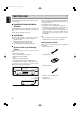
Note
• Do not plug in the mains cord until all connections have
been completed.
• When making connections, also refer to the operating
instructions of the other components.
• Be sure to connect the left and right channels properly
(left with left, right with right).
• Note that binding pin-plug cords together with mains cords
or placing them near a power transformer will result in
generating hum or other noise.
• Even if an external AM antenna is used, do not disconnect
the AM loop antenna.
• Make sure AM loop antenna lead terminals do not touch
metal parts of the panel.
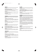
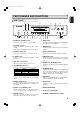
CONNECTIONS
Note
Connect the tuner to other equipment in the below sequence to use the tuner.
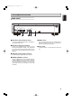
1. Connect an FM antenna to the FM ANTENNA A terminal.
2. Connect an AM loop antenna to the AM ANTENNA terminals. The terminals do not have a particular polarity.
3. Connect the LINE OUT and REMOTE CONTROL connectors to their corresponding terminals on a stereo amplifier using
the provided cords. (Turn power to the stereo amplifier OFF before making the connections.)
4. Plug the power cable of the tuner into a power outlet.
5. This completes connections. Point the antennas in a direction of good reception.
PHONO TAPE 2AUXTUNER TAPE 1
CD
L
R
L
R
SPEAKER SYSTEMS 1
SPEAKER SYSTEMS 2
L R
REMOTE
CONT.
OUT
IN
AC OUTLETS
AC 120V 60HZ
SYSTEM 1: MINIMUM 8 OHMS
L R
SYSTEM 2: MINIMUM 8 OHMS
SYSTEM 1 AND 2: MINIMUM 16 OHMS
SWITCHED
1.0 A 120W
MAX
UNSWITCHED
1.0 A 120W
MAX
OUT
IN
OUT
IN
RCA Pin Plug Cord
(Provided)
RCA Pin Plug Cord
(Provided)
To AC Outlet
Stereo Amplifier
Tuner
AM(MW)Indoor Loop Antenna
(provided)
Roof-top FM Antenna(75 ohms)
Matching
Transformer
(optional)
Lead-type FM Antenna(75 ohms)
(provided)
AM(MW)Outdoor Antenna
5 to 12m
75‰ 75‰
FM ANTENNA B
AM
AM ANTENNA
FM ANTENNA A
GND
RESET
REMOTE
LINE OUT
L
R
CONTROL
CAUTION:
Do not plug the power cord of any
component into AC outlets and do not
turn their POWER switches on until
connections have been performed.
7
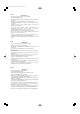
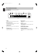
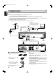
Assembling the AM loop antenna
1. Take out the connection
line.
2. Bend the base part in the
reverse direction.
3. Insert the hook at the
bottom of the loop part into
the slot at the base part.
4. Place the antenna on a
stable surface.
ST6001N 01 Eng 06.1.20 10:34 AM ページ6