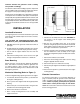
PANCAKE CAPACITOR GENERATOR Installation, Operation, and Maintenance Manual
TABLE OF CONTENTS General Data INTRODUCTION . . . . . . . . . . . . . . . . . . . . . . . . . . . . . 2 General Data . . . . . . . . . . . . . . . . . . . . . . . . . . . . . . 2 Initial Inspection . . . . . . . . . . . . . . . . . . . . . . . . . . . . 2 Construction: Capacitor Excitation Speed: 60 Hz 1850 rpm at no load 1800 rpm at full load 50 Hz 1550 rpm at no load 1500 rpm at full load SAFETY . . . . . . . . . . . . . . . . . . . . . . . . . . . . . . . . . . . 2 INSTALLATION . . . . . . . . . .
terminals whenever the generator’s shaft is rotating and proceed accordingly. Use extreme caution when handling capacitors. A potential shock condition exists even when the engine has shut off. See page 4 for the proper handling of capacitors. This manual is not intended to be a substitute for properly trained personnel. Installation and repairs should only be attempted by those qualified and trained. The cautions and warnings point out known conditions and situations that are potentially hazardous.
OPERATION Capacitor Excitation/Voltage Regulation A single capacitor is used to regulate the voltage to within 5% of the rated load. Use extreme caution when handling capacitors. The capacitor will still contain high voltage even after the engine has stopped operating. Initial Start-up a. Carefully inspect the generator before start-up. Check all electrical connections, and ensure that all bolts have been securely fastened. Always discharge the capacitor before handling.
Checking Diodes f. If residual voltage is normal, the capacitor is defective and should be replaced. a. Check each diode individually by removing the (+) rotor lead stud connection (see Figures 2 and 3). Diodes are good if the resistance reading is approximately midscale on the lowest ohm rating. b. Check for leakage in each diode by reversing their polarity. Diodes are good if the resistance reading is infinite. A faulty diode will give a resistance value of zero. c.
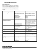
TROUBLE SHOOTING Visual Examination Inspect the generator visually. Look for obvious damage such as: Charred windings, pinched wires, cracked insulation, loose terminal lugs, etc. All connections should be fastened securely. Check the operating speed and see that the unit has been reassembled and reconnected correctly. SYMPTOM Will not hold voltage - Loss of residual magnetism CAUSE Unit has been stored. SOLUTION Flash Rotor (see SERVICE section). Rotor shorting out when unit gets hot.
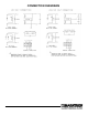
CONNECTION DIAGRAMS 7
Marathon Electric Mfg. Corp. 100 East Randolph Street P.O. Box 8003 Wausau, WI 54402-8003 Phone: (715) 675-3359 Fax: (715) 675-8026 Printed in U.S.A.