MAGNUM ROUTER User’s Guide Release 2.0 marathonstore.
II
About this Guide The Magnum Router User’s Guide describes how to install and configure the Magnum Router. The Magnum Router is shipped with the Magnum GUI (graphical user interface) Manager, a configuration and management software for Windows 95, 98, 2000, ME, XP and NT Workstation 4.0. The Magnum Router GUI Manager and all its features are detailed throughout this guide. Additionally, this guide provides a brief introduction to Frame Relay and offers sample configurations.
Conventions Used in the Manual Throughout this user manual, some information is outlined to inform of important items regarding the section. Text with this icon is to inform of cautionary information Text with this icon is to inform of general information Text with this icon is to inform of information that could cause errors if programmed or used incorrectly Text Bolded and Italicized text will denote a command button or a menu item in the Magnum Router Manager.
Table of Contents CHAPTER 1: INTRODUCTION ................................................................1-1 About the Magnum Router ..........................................................................................1-1 CHAPTER 2: MAGNUM ROUTER FEATURES ......................................2-1 Magnum Router Specifications ..................................................................................2-2 Installation Requirements ..................................................................
CHAPTER 7: MAGNUM ROUTER GUI MANAGER ................................7-1 Magnum Router Manager Main Screen ......................................................................7-2 Toolbar Buttons .......................................................................................................7-2 New Config Button .................................................................................................7-3 Port Config Button.......................................................................
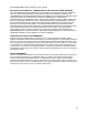
END USER License Agreement (EULA) END USER LICENSE AGREEMENT FOR MAGNUM ROUTER MANAGER SOFTWARE IMPORTANT READ CAREFULLY: This End-User License Agreement ("EULA") is a legal agreement between you (either an individual person or a single legal entity, who will be referred to in this EULA as "You") and the Licensor for the Magnum Router technology that displays this EULA, including any associated media, printed materials and electronic documentation (the "Software").
No rental, leasing or commercial hosting. You may not rent, lease, lend or provide commercial hosting services to third parties with the Software. Support Services. Licensor may provide You with support services related to the Software ("Support Services"). Use of Support Services is governed by the policies and programs described in the user manual, in "online" documentation, or in other materials from the support services provider.
NON-INFRINGEMENT WITH REGARD TO THE Software. EXCLUSION OF INCIDENTAL, CONSEQUENTIAL AND CERTAIN OTHER DAMAGES. TO THE MAXIMUM EXTENT PERMITTED BY APPLICABLE LAW, IN NO EVENT SHALL WESTERN NRG, INC.
X
Chapter 1: Introduction ___________________________________________________________________ Chapter 1: Introduction Introduction Congratulations on your purchase of the Magnum Router Module. The Magnum Router Module is a high performance IP Router and Frame Relay Switch. With the Frame Relay Switch, you can create a private network, access a public frame relay service, or build an integrated hybrid network with multiple carriers, offering public and private services.
Chapter 1: Introduction ___________________________________________________________________ 1-2
Chapter 2: Magnum Router Features ___________________________________________________________________ Chapter 2: Magnum Router Features Scaleable The Magnum Router’s 4 Serial WAN architecture allows enterprise networks to scale from multipoint frame relay networks to multiple dedicated digital networks or a hybrid network of carrier frame relay and dedicated networks. Marathon Modularity Field installable in any new or existing Marathon or Netrunner with software version 5.0 or greater.
Chapter 2: Magnum Router Features ___________________________________________________________________ Magnum Router Specifications Microprocessor Motorola MPC-860T, 50Mhz Standard Compliance T1.617 ANNEX-D, ITU Q933-ANNEXA Memory ITU I.233, ANSI T1.606 64 MB SDRAM, 2MB FLASH, 16MB FLASH DISK-ON-CHIP ITU Q922-ANNEXA, ANSI T1.618 Interface Connections Management Options One male DB 25 V.35 (M1), Three male DB25 V.
Chapter 2: Magnum Router Features ___________________________________________________________________ Installation Requirements The following items will be required to install and operate the Magnum Router module: • • • • A Marathon base unit. The Magnum GUI Manager software (included), running on a PC with Microsoft Windows 95, 98, 2000, ME, XP or NT workstation 4.0. An available PC COM port.
Chapter 2: Magnum Router Features ___________________________________________________________________ 2-4
Chapter 3: Pre-Installation ___________________________________________________________________ Chapter 3: Pre-Installation Planning and Preparation Installing and configuring a Magnum Router module / Marathon system takes some up-front planning. It is advisable to consider a number of configurations before deciding on the one that is best for the specific application.
Chapter 3: Pre-Installation ___________________________________________________________________ The following items are also helpful (if not critical) for the planning phase to be completed: • • • • • Determine the Name of your Magnum Router Determine the WAN Configuration (Port Settings) Determine the Master WAN IP Address Determine the WAN-IP Route Map information Determine the Ethernet Port IP Address Planning Worksheets Located in chapter 13 is configuration planning worksheets to assist in the progra
Chapter 4: Installing the Hardware ___________________________________________________________________ Chapter 4: Installing the Hardware Cable Kit Notes The cable kit M5000M/RK-1 will work with any Marathon base unit, however if the Marathon base unit that the Magnum Router is being installed into is a 75e, 3K, 5KT Pro or a 20K Pro; then it is important that the jumper settings for the A1 port be set for RS-232 operation.
Chapter 4: Installing the Hardware ___________________________________________________________________ 5. Connect the appropriate M1 to A1 cable from the M1 port of the Magnum Router to the A1 port of the Marathon base unit. Connect the appropriate WAN port cables to their respective CSU/DSU’s Connect the manager console cable. 6. Power on the equipment. This completes the hardware installation of the Magnum Router.
Chapter 5: Magnum Router Manager Installation ___________________________________________________________________ Chapter 5: Magnum Router Manager Installation About the Manager Software The Magnum Router GUI Manager is a configuration and management software for the Magnum Router that runs on Windows. The Manager functions much the same as other Windows programs. The following will be required to install the software: • The Magnum Router GUI Manager installation disk.
Chapter 5: Magnum Router Manager Installation ___________________________________________________________________ After the pre-installation screen has completed any checking, the main installation screen will be displayed: Figure 2 - Setup Confirmation Screen Click on OK to continue the installation, or click Exit Setup to abort the installation. If OK was clicked, the select directory/perform installation screen will be displayed.
Chapter 5: Magnum Router Manager Installation ___________________________________________________________________ Click on the Setup button at the top of the screen to continue the installation. Figure 4 - Setup Program, Program Group During the installation, the setup program will request a program group. By default, the program group is Magnum Router Manager. Enter another Program Group name, select one from the list, or click on Continue to proceed.
Chapter 5: Magnum Router Manager Installation ___________________________________________________________________ Once the installation process has completed, the setup program will display the following message: Figure 6 - Setup Program, Installation Complete Screen Click on OK to return to the windows desktop. Upgrading the Magnum Router Manager If an earlier version of the Magnum Router manager has already been installed on the PC, it has to be removed before installing the newer version.
Chapter 5: Magnum Router Manager Installation ___________________________________________________________________ First-Time Startup When the Magnum Router Manager first starts, it looks for setup information. If this is the first time that you’re running the manager, the communication port settings screen will appear.
Chapter 5: Magnum Router Manager Installation ___________________________________________________________________ 5-6
Chapter 6: Logging Onto a Magnum Router ___________________________________________________________________ Chapter 6: Logging Onto a Magnum Router After the initial installation of the Magnum Router Manager software and it’s setup, the main login screen is displayed. This screen is only displayed when the Magnum Router Manager is first started or when the Login to a Magnum Router menu item is selected from the Access menu.
Chapter 6: Logging Onto a Magnum Router ___________________________________________________________________ Marathon Matrix Cabling It is possible to connect to a Magnum Router through a Marathon Async port either by direct cable connection or by modem connection. In order to perform a Marathon Matrix connection, there must be 2 available Async ports on the Marathon base unit. Further, this will require 2 cables.
Chapter 6: Logging Onto a Magnum Router ___________________________________________________________________ Modem Connection Cabling To connect a Modem to the Magnum Router, some preparation is required to ensure that the Modem and the Magnum Router communicate properly. The external modem must be a Hayes compatible type (responds to the AT command set) in order for a modem connection to be established. First, attach a cable from a PC or a dumb terminal to the modem.
Chapter 6: Logging Onto a Magnum Router ___________________________________________________________________ Magnum Router Login Screen Bypass the LOGIN Process and go directly to the Magnum Router Manager Main Screen Connect to a Magnum Router using the selected LOGIN METHOD Start the TEXT ONLY terminal program De-Select this ONLY if the Magnum Router's access password has been changed Different METHODS to login to a Magnum Router Input the new Magnum Router access password here IF it has been changed
Chapter 6: Logging Onto a Magnum Router ___________________________________________________________________ Console Login The default for logging onto a Magnum Router is a serial connection from the PC that is running the Magnum Router Manager software to a Magnum Router card. The connection is accomplished by connecting either the supplied DB-9 to DB-25 straight thru cable (or equivalent) from the PC to the Magnum.
Chapter 6: Logging Onto a Magnum Router ___________________________________________________________________ Telnet This allows Ethernet access to the Magnum Router. additional section to the main login screen.
Chapter 6: Logging Onto a Magnum Router ___________________________________________________________________ Micom Marathon Matrix This gives the ability to connect to the Magnum Router’s console port via a Micom Marathon matrix connection. This connection is done by a NODE/CHANNEL connection type.
Chapter 6: Logging Onto a Magnum Router ___________________________________________________________________ Below is an example of connecting a PC to the Marathon unit, and connecting the Marathon unit to the Magnum Router. Marathon Node Name: TOP M5000C/MATRIX M5000C/CP PC To use a login method of Marathon Matrix for the above example, fill in the fields as shown below.
Chapter 6: Logging Onto a Magnum Router ___________________________________________________________________ Modem By default, the Magnum Router manager does not send any command strings to the attached modem. In some cases, it is necessary to send special commands to the PC’s modem in order to make it work properly. The Magnum Router Manager has the ability to send up to 5 of these special commands.
Chapter 6: Logging Onto a Magnum Router ___________________________________________________________________ From this point on, the Magnum Router Manager will send the entered commands before dialing the selected number. If there is a modem change on the PC that is running the Magnum Router Manager, then these commands may be changed or deleted. Dialing to a Magnum Router Start the Magnum Router Manager and select Modem in the Login Method box. After selecting Modem, click on the Connect button.
Chapter 6: Logging Onto a Magnum Router ___________________________________________________________________ Magnum Router Manager Phone Directory Figure 11 - Magnum Router Phone Directory Screen All information entered in the Phone Directory is independent from the other settings of the Magnum Router Manager. Meaning that the COM port selected in the Phone Directory can be the same or different from the one selected in the Communications Settings screen.
Chapter 6: Logging Onto a Magnum Router ___________________________________________________________________ Changing a Phone Directory Entry It is possible to change an entry after it has been entered into the table. Follow these steps to change an entry: 1. Double-Click on the entry that needs modification in the table This will cause all of the entry data to be loaded in the fields above the table. 2. Make any modifications required 3. Click on Save Edit or press ALT-V 4.
Chapter 6: Logging Onto a Magnum Router ___________________________________________________________________ Upon a successful connection, the Magnum Router Manager’s status will change and reflect that there is a MODEM connection as shown below. If an error occurs during the modem connection, an error message will appear. One possible error is shown below. Terminating a Dial Up Terminating a modem connection to a Magnum Router can be accomplished in 2 ways. (1) Exit the Manager.
Chapter 6: Logging Onto a Magnum Router ___________________________________________________________________ Login Messages After selecting the desired login method, select connect by either clicking on Connect, or pressing ALT-C. If Modem was selected, the dialing directory will appear (see above), but if any other method was selected, the status screen will be displayed. This screen is for informational purposes, just to show the status of the login process.
Chapter 6: Logging Onto a Magnum Router ___________________________________________________________________ If Yes was selected, the following screen will appear, reporting that the manager is getting the connected Magnum Router’s stored configuration. Other Login Screen Options There are 2 other buttons on the login screen. Select this button by either clicking on it, or pressing ALT-D. This will bypass the login process and will then show the Magnum Router Manager main screen.
Chapter 6: Logging Onto a Magnum Router ___________________________________________________________________ Magnum Router Manager Terminal This option opens a text-based terminal. This can be used to program optional equipment (such as a Micom Marathon) without having to exit the Magnum Router Manager. It is NOT a VT100 terminal emulator. This means that special control characters are not recognized and will be displayed. As an example, it could be used to access a Micom Marathon to check the unit status.
Chapter 6: Logging Onto a Magnum Router ___________________________________________________________________ Selecting Activate Terminal will display the Magnum Router Manager terminal screen. Figure 12 - Magnum Router Manager Terminal Screen The terminal program has an internal scroll back buffer of 4000 bytes, the ability to capture incoming data to a file and the ability to send a “break” sequence to a device. It does NOT include any file transfer capabilities.
Chapter 6: Logging Onto a Magnum Router ___________________________________________________________________ Magnum Router Manager Terminal Commands As seen in the above screen, the terminal has 3 basic commands: This sends a “break” sequence to the attached device. As an example, it is required to send 3 “break” sequences to terminate a Marathon Matrix connection. Each time this button is clicked, the terminal program will show “Break Sent” in the display when it has completed the task.
Chapter 7: Magnum Router GUI Manager ___________________________________________________________________ Chapter 7: Magnum Router GUI Manager The Manager User Interface The Magnum Router GUI Manager uses a graphical user interface common to most Windows programs. Movement around the manager is done by either clicking the button or menu item, using shortcut keys (as shown by an underscore under a letter or a menu or button), or using the tab key.
Chapter 7: Magnum Router GUI Manager ___________________________________________________________________ Magnum Router Manager Main Screen Menu Bar Toolbar Magnum Name. Display's the name assigned to the Magnum Router that the Manager is currently logged into Remote Access. This ONLY shows when a Magnum Router is being remotely accessed. Connection Type. Display's how the Magnum Router Manager is connected to a Magnum Router Transmit Data. Flashes RED when data is sent. Receive Data.
Chapter 7: Magnum Router GUI Manager ___________________________________________________________________ New Config Button This button can be accessed by pressing ALT-N, or selecting New Configuration from the Configuration menu. Select this button to create an empty configuration in the Magnum Router Manager customization. Selecting this item will cause the Set Mangum Name screen to appear Figure 15 - Set Magnum Name Screen This sets the name of the Magnum Router.
Chapter 7: Magnum Router GUI Manager ___________________________________________________________________ Port Config Button Select Port Config to configure the physical and logical characteristics of the WAN ports of the Magnum Router (the WAN ports are M1, WAN1, WAN2 and WAN3). Physical characteristics determine whether the port is DTE (accepts clock), DCE (supplies clock) and port speed. Logical characteristics include the Frame Relay LMI type and the Frame Relay link type.
Chapter 7: Magnum Router GUI Manager ___________________________________________________________________ Below is a description of the fields on this screen: Port Selects the port to be configured. Mode Configures the port as physical DCE (supplies clock), DTE (receives clock), or Disable (disables the port altogether). Disable is recommended if the port will not be in use. Link Type Specifies the logical interface for the Magnum Router port. Select from the options in the list box.
Chapter 7: Magnum Router GUI Manager ___________________________________________________________________ Baud Rate Sets the baud rate for the selected port. Choose from the baud rates available in the drop down list box. Baud Rate Notes A baud rate denotes the speed of which a serial port is to operate at. The Magnum Router handles baud rates in the following manner: When the Port Mode is selected as DCE, then the baud rate selected is the reported clock speed to the attached device.
Chapter 7: Magnum Router GUI Manager ___________________________________________________________________ WAN Config Button Click the WAN Config button on the Magnum Router Manager main screen, press ALT-W, or select WAN Configuration from the Settings menu to access the WAN Configuration screen. In a frame relay environment, end-points are connected together via the use of PVC’s (Permanent Virtual Circuits). The WAN Configuration screen is where these PVC connections are created in the Magnum Router.
Chapter 7: Magnum Router GUI Manager ___________________________________________________________________ The Input and Output port fields of the WAN Configuration screen define the physical ports of the Magnum Router. The Private and Public DLCI fields define the DLCI end-points of a PVC. A PUBLIC DLCI would (in most cases) be the DLCI that is being supplied by the Frame Relay provider.
Chapter 7: Magnum Router GUI Manager ___________________________________________________________________ Deleting a WAN Configuration Entry In some cases, a WAN entry may need to be deleted. To do this, follow these steps: 1. Select an entry in the table. 2. Either click the Delete Entry button or press ALT-D. 3. A verification question is asked to make sure that this is the entry to delete, if it is, select Yes. Selecting No will return to the WAN Configuration screen.
Chapter 7: Magnum Router GUI Manager ___________________________________________________________________ Master WAN-IP Address The Master WAN-IP address screen is only available via the WAN Configuration screen. The Magnum Router is a Frame Relay switch and IP router combined into a single product. The Master WAN-IP address screen allows users to configure a single WAN interface or multiple WAN sub-interfaces by mapping and assigning a unique IP network number to specific DLCI’s.
Chapter 7: Magnum Router GUI Manager ___________________________________________________________________ Adding a Master WAN-IP Address Entry To add an entry in the Master WAN-IP screen, perform the following steps: 1. 2. 3. 4.
Chapter 7: Magnum Router GUI Manager ___________________________________________________________________ WAN-IP Route Map The WAN IP Route Map screen is only available via the WAN Configuration screen. The next step will be to fill data into the WAN-IP Route Map screen. The purpose of the WANIP Route Map is to set the destination network address with its corresponding DLCI number, port number and associated gateway (a.k.a. next hop IP address).
Chapter 7: Magnum Router GUI Manager ___________________________________________________________________ Adding a WAN IP Route Map Entry To add an entry in the WAN IP Route Map screen, perform the following steps: 1. Click New Entry and select the Ethernet 1 port 2. Enter the appropriate private DLCI number, destination network IP address and subnet mask and corresponding gateway (a.k.a. next hop IP address) 3. Click Save Edit or press ALT-V to save the entry 4.
Chapter 7: Magnum Router GUI Manager ___________________________________________________________________ Advanced Routing This function is only available via the WAN-IP Route Map screen. The Advanced Routing section of the Magnum Router Manager allows for additional static routes to be entered. Such routes may include a default route to another router for internet access. Click on the Advanced Routing button of the WAN IP Route Map screen, or press ALT-A to display the Advanced Routing screen.
Chapter 7: Magnum Router GUI Manager ___________________________________________________________________ Adding an Advanced Routing Entry To add an entry in the WAN IP Route Map screen, perform the following steps: 1. Click New Entry or press ALT-N 2. Enter data in the IP Address, Subnet Mask, and Gateway Address fields 3. Click Save Edit or press ALT-V to save the entry 4. Click Exit Edit or press ALT-X to return to the WAN IP Route Map screen.
Chapter 7: Magnum Router GUI Manager ___________________________________________________________________ RIP Version 1 Routing Enable RIP routing by clicking on the box next to Enable RIP Version 1 Routing. To disable RIP routing, remove the check in the box. The Magnum Router implements the RIP routing protocol in a “hybrid” fashion. It is covered in more detail in chapter 8.
Chapter 7: Magnum Router GUI Manager ___________________________________________________________________ Ethernet Config Button Select this button to program IP addresses on the Ethernet port of the Magnum Router. This can be accessed by pressing ALT-E, and is also available as Ethernet Configuration from the Settings menu. This section of the Magnum Router Manager allows for the entry of IP addresses on the E1 (Ethernet) port of the Magnum Router.
Chapter 7: Magnum Router GUI Manager ___________________________________________________________________ Adding an Ethernet IP Entry To add an entry in the Ethernet IP screen, perform the following steps: 1. Click New Entry or press ALT-N 2. Enter data in the IP Address and Subnet Mask fields 3. Click Save Edit or press ALT-V 4. Click Exit Edit or press ALT-X Changing an Ethernet IP Entry It is possible to change an entry after it has been entered into the table. Follow these steps to change an entry: 1.
Chapter 7: Magnum Router GUI Manager ___________________________________________________________________ Micro-Band Voice Over IP The MVoIP function of the Magnum Router gives the ability to encapsulate any frame relay data that is supplied on any of the WAN ports into a routable IP packet that can be sent over any IP LAN environment (including the Internet). Before programming any data into the MVoIP screen, certain requirements must be met.
Chapter 7: Magnum Router GUI Manager ___________________________________________________________________ MVoIP Requirements The requirements to add an MVoIP entry include an entry in the WAN configuration using a DLCI of 900 thru 989 and an output port of E1; a WAN IP Route Map entry that uses a DLCI from 900 thru 989, and an Ethernet Configuration entry. If any of these requirements are not met, the Magnum Router Manager will report an error if the MVoIP button is clicked.
Chapter 7: Magnum Router GUI Manager ___________________________________________________________________ DHCP Server The Magnum Router has the ability to act as a local DHCP server in a network environment. It cannot function as an enterprise level DHCP server, pass DHCP traffic across any of its WAN ports, does not support BOOTP processing and does not support multiple scopes. Making the Magnum Router the local DHCP server eliminates unneeded WAN traffic while IP hosts make requests for information.
Chapter 7: Magnum Router GUI Manager ___________________________________________________________________ Programming the Magnum Router as a DHCP server, it will supply to the local IP host device such things as an IP address, WINS addresses (up to 3), DNS addresses (up to 3), Domain Name and default gateway information. Programming the DHCP server requires that an IP address be entered in the Ethernet Configuration screen.
Chapter 7: Magnum Router GUI Manager ___________________________________________________________________ If all data entered is correct, click on Exit to close the DHCP screen. If not, correct the data and click on Save again. To disable the DHCP server, click on the box next to Enable DHCP Server to remove the check and click on Save.
Chapter 7: Magnum Router GUI Manager ___________________________________________________________________ DHCP IP Scope As with other DHCP servers, the IP scope (DHCP Range From Address and DHCP Range To Address) need to be within the same subnet as the host IP address and cannot overlap the host IP address.
Chapter 7: Magnum Router GUI Manager ___________________________________________________________________ DHCP Functions Other buttons on this screen are: Select this button to clear all the fields on the screen.
Chapter 7: Magnum Router GUI Manager ___________________________________________________________________ Save Configuration This option saves the current configuration in the Magnum Router Manager. (See Save Config notes later in this chapter for important information) This can also be accessed by pressing ALT-V, and is also available as Save Configuration from the Configuration menu.
Chapter 7: Magnum Router GUI Manager ___________________________________________________________________ Save Configuration Notes As of version 2.x of the Magnum Router Manager, configuration files are saved with a “.cf2” extension, where previous versions of the Magnum Router Manager saved files with a “.cfg” extension. It is possible to save any configuration as either a version 1 (.cfg) or version 2 (.cf2) format – it is strictly up to the user.
Chapter 7: Magnum Router GUI Manager ___________________________________________________________________ It is at this time that the Send Config can be canceled by clicking No and going back to the appropriate section of the Magnum Router Manager and applying any fixes necessary, or this warning can be ignored by pressing Yes. If Yes was selected, the following screen will appear: Click Send to send this configuration to the Magnum Router, or click Cancel to return to the Magnum Router main screen.
Chapter 7: Magnum Router GUI Manager ___________________________________________________________________ Click on the Reboot Router or press ALT-R and the following screen will appear: By clicking Yes, the reboot process will begin. It takes approximately 2 minutes to complete a reboot, and after the reboot is complete, the Magnum Router Manager will automatically log back onto the Magnum Router.
Chapter 7: Magnum Router GUI Manager ___________________________________________________________________ Menu Bar Figure 25 - Main Screen Menu Bar The Menu Bar allows for more detailed access to the Magnum Router GUI Manager commands and functions. Select one of the Menu Bar items by clicking on it, or by pressing it’s shortcut key (shown by an underline under a character in the menu item description when the ALT key is pressed). All of the toolbar buttons are also located in various menu’s.
Chapter 7: Magnum Router GUI Manager ___________________________________________________________________ Remotely Access a Magnum Router This menu item is used to access another Magnum Router within the network. This menu item is only available if the Magnum Router Manager is currently logged onto a Magnum Router. Remotely Access a Magnum Router Select this function to access a remote Magnum Router.
Chapter 7: Magnum Router GUI Manager ___________________________________________________________________ If an error occurs during a remote login attempt, the following screen will be displayed: Clicking OK will then re-log the Magnum Router Manager onto the local Magnum Router. Logoff a Remotely Accessed Magnum Router This menu item terminates a login from a remotely accessed Magnum Router. This menu item is only available if the Magnum Router Manager is currently logged onto a remote Magnum Router.
Chapter 7: Magnum Router GUI Manager ___________________________________________________________________ Configuration Menu (ALT-C) Figure 27 - Main Screen Configuration Menu New Configuration File This menu item is the same as clicking on the “New Config” button of the main screen. All settings within the Magnum Router Manager are defaulted and the “Set Magnum Name” screen will be displayed. Opening Configuration File You can access a configuration file saved on your hard drive.
Chapter 7: Magnum Router GUI Manager ___________________________________________________________________ At noted in chapter 7, version 2.x of the Magnum Router Manager saves files with a “.cf2” extension. This is the default. If a version 1.x configuration file needs to be opened, click on the down arrow next to the Files of type box and select Magnum Configuration 1.x (*.cfg) option and the version 1.x configuration files will be displayed.
Chapter 7: Magnum Router GUI Manager ___________________________________________________________________ Printing a Configuration Select this option to print or view a copy of the working configuration that is loaded in the Magnum Router Manager.
Chapter 7: Magnum Router GUI Manager ___________________________________________________________________ The Select Printer field loads all the printers loaded into the PC that is running the Magnum Router Manager. Select the appropriate printer from the dropdown box. Select the fields to print, the printer orientation and the number of copies to print, a report title and select either Print or Preview.
Chapter 7: Magnum Router GUI Manager ___________________________________________________________________ Send Configuration to the Magnum Router This option is the same as clicking on the “Send” button of the main screen. It’s function is to send the configuration that is currently being worked on in the Magnum Router Manager to the Magnum Router. Sending the configuration to the Magnum Router does not cause the Magnum Router to begin using any changes instantly.
Chapter 7: Magnum Router GUI Manager ___________________________________________________________________ Remote Magnum Names The Magnum Router Manager gives users the ability to associate a name with an IP address, thus making it an easier task to connect to a remote node, or ping a remote site. Select REMOTE MANGUM NAMES and the following screen will be displayed. Figure 30 - Remote Names Screen Adding a Remote Name Entry To add an entry in the Router Names screen, do the following steps: 1. 2. 3. 4.
Chapter 7: Magnum Router GUI Manager ___________________________________________________________________ Changing a Remote Name Entry It is possible to change an entry after it has been entered into the table. Follow these steps to change an entry: 1. Double-Click on the entry that needs modification in the table This will cause all of the entry data to be loaded in the fields above the table. 2. Make any modifications required 3. Click on Save Edit or press ALT-V 4.
Chapter 7: Magnum Router GUI Manager ___________________________________________________________________ System Menu (ALT-Y) Figure 31 - Main Screen System Menu This menu is concerned with system level functions of the Magnum Router. This menu is ONLY accessible if the Magnum Router Manager is logged onto a Magnum Router. Reboot Router Selecting the Reboot Router menu item is the same as clicking on Reboot Router from the main screen.
Chapter 7: Magnum Router GUI Manager ___________________________________________________________________ The following screen will be displayed: Click Continue to proceed, or click Exit to return to the Magnum Router Main Screen. Once the upgrade process has started, it cannot be stopped.
Chapter 7: Magnum Router GUI Manager ___________________________________________________________________ As stated in the above screen, the upgrade program needs to use the Microsoft FTP program that is supplied with the Windows operating system. If the FTP program on the PC that is running the Magnum Router Manager uses a third party FTP client program, then a manual upgrade will be required.
Chapter 7: Magnum Router GUI Manager ___________________________________________________________________ The next step is to inform the Magnum Router Manager where to find the update files. Do this by selecting the hard disk and directory where the Update files were de-compressed. The Magnum Router Manager will then verify that the upgrade files are correct.
Chapter 7: Magnum Router GUI Manager ___________________________________________________________________ After copying the files from the PC to the Magnum Router, the Magnum Router Manager verified that all of the files have been copied correctly. If there is an error, the following will be displayed: If this error appears, click on OK and try the upgrade process again. Once the files have been verified, the Magnum Router Manager will try and access the Magnum Router.
Chapter 7: Magnum Router GUI Manager ___________________________________________________________________ This display is to let the user know that the file transfer has completed, and the update is proceeding by processing a specific set of commands. Figure 33 - Upgrade Magnum Router, Process Upgrade Commands Screen Once all steps have been completed, a message will display signifying that the upgrade has completed. Click on OK to return to the Magnum Router Manager Main Screen.
Chapter 7: Magnum Router GUI Manager ___________________________________________________________________ Diagnostics The DIAGNOSTIC screen gives a simple set of tools to check connectivity, DLCI status, and IP Routes on a Magnum Router. Below is the overview of the DIAGNOSTIC screen.
Chapter 7: Magnum Router GUI Manager ___________________________________________________________________ PING The most used test function on a router is the PING command. This command allows for the verification that a specified IP Host device is active. To perform the PING command from the DIAGNOSTICS screen, enter either the IP address of the IP host, or select it from the Router Name field. Other options for the PING command include the PING packet size and the number of PING’s to perform.
Chapter 7: Magnum Router GUI Manager ___________________________________________________________________ To stop a PING at any time, either click on EXIT or STOP.
Chapter 7: Magnum Router GUI Manager ___________________________________________________________________ If the IP Host that is being PING’ed does not respond to requests within 10 seconds, the PING command automatically terminates and the following screen is displayed: 7-49
Chapter 7: Magnum Router GUI Manager ___________________________________________________________________ Show IP Routes The Show IP Routes command shows any routes that have been programmed into the Magnum Router. It does not differentiate between static routes or routes that have been dynamically learned.
Chapter 7: Magnum Router GUI Manager ___________________________________________________________________ List DLCI’s The List DLCI’s command is used to report the DLCI’s that have been reported on each port. This includes any that have been programmed, and any that have been learned from any other source. This screen just reports the DLCI’s, it DOES NOT display detailed DLCI information, use the Display Port Statistics command in the Statistics menu for detailed DLCI status information.
Chapter 7: Magnum Router GUI Manager ___________________________________________________________________ Change Access Password In some cases, it may be necessary to change the default access password of a specific Magnum Router. ALTHOUGH IT IS NOT RECOMMENDED, the Magnum Router Manager has the ability to change the default access password to any other password, so long as the length of that password is greater than 6 characters.
Chapter 7: Magnum Router GUI Manager ___________________________________________________________________ Once all fields have been entered, click on Save (or press ALT-V) and then click on Exit (or press ALT-X. The first warning message will be displayed: Selecting Yes will then display a second warning message Selecting Yes again will then change the access password of the Magnum Router. Selecting No on either of the warning messages will return to the Main Screen.
Chapter 7: Magnum Router GUI Manager ___________________________________________________________________ Statistics Menu (ALT-T) Figure 39 - Main Screen Statistics Menu This menu is used to show the current condition of the Magnum Router. Port status, link information and Magnum Router utilization are just some of the items available for display from this menu. This menu is ONLY accessible if the Magnum Router Manager is logged onto a Magnum Router.
Chapter 7: Magnum Router GUI Manager ___________________________________________________________________ Display Port Statistics Figure 40 - Port Statistics Screen The Port Statistics screen gives the ability to monitor port status and see how each port is transferring data. Next to each port is a drop-down box that can also give the added ability to monitor specific DLCI’s on a port, or all DLCI’s of a port. The ability to monitor a specific DLCI gives “drill-down” diagnostics of the health of a circuit.
Chapter 7: Magnum Router GUI Manager ___________________________________________________________________ Clearing the Statistics Counter Click on the Clear Counters (or press ALT-C) to perform a clearing of the counters. This action ONLY clear counters on the WAN ports of the Magnum Router, not the Ethernet port.
Chapter 7: Magnum Router GUI Manager ___________________________________________________________________ DLCI State Information As seen in the above screen, the Detailed Port Information screen reports DLCI’s that have been either programmed or reported on the port specified in the Port dropdown box.
Chapter 7: Magnum Router GUI Manager ___________________________________________________________________ Display Magnum Utilization The Display Magnum Utilization screen gives the ability to show the Magnum Router status in both a text and graphical format. It also has the ability to capture the sampled data to a file (in a comma separated format). The graphical display shows performance in both a BAR chart format and a LINE chart format.
Chapter 7: Magnum Router GUI Manager ___________________________________________________________________ As can be seen in the previous screen shot, this is a very comprehensive data display that requires some time to actually load and compare all data received. In some cases, it may take several seconds when this function is actually selected before data is displayed. This screen is broken into 3 sections; The Menu bar, the Chart Section and the Data section.
Chapter 7: Magnum Router GUI Manager ___________________________________________________________________ The captured data is saved in a comma-separated format (.CSV) that can easily be imported into another application such as Excel. Using the captured data, it would then be easy to plot such thing as bandwidth usage over a given amount of time. Chart Menu This display supports 2 types of charts supported, BAR and LINE.
Chapter 7: Magnum Router GUI Manager ___________________________________________________________________ Chart Section Overview As stated earlier, there are 2 different types of charts allowed in this display; BAR and LINE. The difference between them is the data that can be displayed. In the case of the BAR chart, all data in the text section can be displayed in a columnar format for each port. In the LINE chart, only 1 column of data can be displayed at a time for the selected ports.
Chapter 7: Magnum Router GUI Manager ___________________________________________________________________ Data Selection Received Bytes Received Frames Transmitted Bytes Transmitted Frames Estimated Bandwidth in use Port Utilization Port Bandwidth Figure 49 - Magnum Utilization Data Selection Bar In the BAR chart mode, all data except the BANDWIDTH can be displayed at one time. In the LINE chart mode, only one data column can be displayed at a time.
Chapter 7: Magnum Router GUI Manager ___________________________________________________________________ Line Chart The LINE chart can show only one column of data for all selected ports. To change the data being displayed on the chart, click on another data column heading. The previous data column will de-select itself and the new selection will be charted.
Chapter 7: Magnum Router GUI Manager ___________________________________________________________________ Port Status Strobe The Port Status Strobe is a convenient way to see each WAN port’s status from the Main screen. It automatically updates every 60 seconds (non changeable) and can supply snapshot information regarding the port status. When selected, a check mark is placed next to the Port Status Strobe menu item. This is used as an indicator as to whether the strobe is active or not.
Chapter 7: Magnum Router GUI Manager ___________________________________________________________________ Figure 54 - Port Status Strobe Snapshot Screen Help Menu Item (ALT-H) Selecting this item shows the Magnum Router Manager version and miscellaneous information that could be helpful in diagnosing problems. Exit Menu Item (ALT-X) Selecting this option closes the Mangum Router Manager program When exiting the Magnum Router Manager, the loaded configuration (a.k.
Chapter 7: Magnum Router GUI Manager ___________________________________________________________________ 7-66
Chapter 8: Magnum Router Specialized Functions ___________________________________________________________________ Chapter 8: Magnum Router Specialized Functions This chapter covers the specialized functions of the Magnum Router. These functions include Virtual Routing of DLCI’s, MVoIP (Micro-Band Voice Over IP) and Hybrid RIP routing. In the case of Virtual Routing and MVoIP, these are proprietary functions and a Magnum Router is required to be at each end-point of a circuit.
Chapter 8: Magnum Router Specialized Functions ___________________________________________________________________ For Example: Below is a simple diagram that could represent one application that would use a virtual DLCI.
Chapter 8: Magnum Router Specialized Functions ___________________________________________________________________ The WAN configuration screen would look like this: What has been accomplished in this example is that the PUBLIC DLCI of 100 now has the capability of sending data from the M1 (Marathon) port and the E1 (Ethernet) port to the remote Magnum Router using a public DLCI of 100. NON-Virtual DLCI’s As noted earlier, the Magnum Router is a Frame Relay switch and an IP router.
Chapter 8: Magnum Router Specialized Functions ___________________________________________________________________ This utilizes the frame switching capabilities of the Magnum Router by directing traffic from the PUBLIC DLCI of 100 to the PRIVATE DLCI of 105 and vice versa. A PUBLIC DLCI cannot be both a virtual DLCI and a “direct connect” DLCI at the same time.
Chapter 8: Magnum Router Specialized Functions ___________________________________________________________________ There is an MVoIP sample in chapter 9 that will assist in clarifying the programming requirements and steps. RIP Routing RIP (Routing Information Protocol) is implemented on the Magnum Router using a “hybrid” approach.
Chapter 9: Sample Configurations ___________________________________________________________________ Chapter 9: Sample Configurations This chapter describes sample configurations available as files on the Magnum Router Manager CD distributed with the Magnum Router Module. The configurations are some of the most common and useful applications for the Magnum Router Module. You can, if you choose, devise many other configurations, and use any of the sample configurations as a starting point.
Chapter 9: Sample Configurations ___________________________________________________________________ Sample 1 - Dedicated Point to Point Network Magnum/Marathon A Magnum/Marathon B Network: 10.1.100.0/24 Network: 172.16.1.0/24 IP Address: 172.16.1.250/24 Ethernet port IP Address: 10.1.100.250/24 Ethernet port A1 to M1 cable CSU/DSU WAN IP Address: 192.168.1.1/24 T1 Network Subnet: 192.168.1.0/24 CSU/DSU WAN IP Address: 192.168.1.
Chapter 9: Sample Configurations ___________________________________________________________________ Below are several screen shots of the Magnum-A and Magnum-B’s configuration. M1 Port Settings for both Magnum A and Magnum B Here, the M1 port is configured to act as a Frame Relay NETWORK port (FR_Dedicated), but to also act as a synchronizing port as well thus is it set for DCE. This means that the M1 port will supply a clocking source of 128k for the attached Marathon.
Chapter 9: Sample Configurations ___________________________________________________________________ WAN1 Port Settings for Magnum A Notice that the WAN1 port is set for DTE and the Link Type is set for DEDICATED_MASTER. As described above, this is the Frame Relay NETWORK port side. Also note that the Baud Rate box that was present for the M1 port has been replaced by a Carrier Rate box. This would be in external clock being supplied by the attached CSU/DSU, in this example 56k.
Chapter 9: Sample Configurations ___________________________________________________________________ WAN1 Port Settings for Magnum B Notice that the WAN1 port is set for DTE and the Link Type is set for DEDICATED_SLAVE. As described above, this is the Frame Relay USER port side.
Chapter 9: Sample Configurations ___________________________________________________________________ WAN Configuration for Magnum A and Magnum B In the above diagram, the main connection between the two sites is a standard DDS line supplied by a carrier. The speed of this line can be anywhere from 9.6k through 2.048m. However this line only supplied clocking information. The Magnum Router must then act as a Frame Relay switch and Frame Relay NETWORK or USER port.
Chapter 9: Sample Configurations ___________________________________________________________________ Master WAN IP Address for Magnum A The following table shows the Master WAN IP Address screen for Magnum A. Master WAN IP Address for Magnum B The following table shows the Master WAN IP Address screen for Magnum B.
Chapter 9: Sample Configurations ___________________________________________________________________ Just like any brand-x router, in order to route IP traffic, there must be an IP address on the WAN port. WAN-IP Route Map Here, the actual routing commands are created to allow Ethernet traffic to flow from Magnum-A to Magnum-B. See Chapter 7 for detailed information on using the Magnum Router Manager to change data in the WAN IP Route Map Table.
Chapter 9: Sample Configurations ___________________________________________________________________ Ethernet Configuration The following window illustrates the Ethernet Configuration associated with this sample configuration.
Chapter 9: Sample Configurations ___________________________________________________________________ Sample 2 - Point to Point Public Frame Relay Network Magnum/Marathon A Magnum/Marathon B Network: 10.1.100.0/24 Network: 172.16.1.0/24 IP Address: 172.16.1.250/24 Ethernet port IP Address: 10.1.100.250/24 Ethernet port DLCI 16 A1 to M1 cable PVC WAN Network 192.168.1.0/24 CSU/DSU IP Address: 192.168.1.1/24 DLCI 17 CSU/DSU IP Address: 192.168.1.
Chapter 9: Sample Configurations ___________________________________________________________________ M1 and WAN1 settings on Magnum-A and Magnum-B In this sample, the port settings of Magnum-A and Magnum-B are identical.
Chapter 9: Sample Configurations ___________________________________________________________________ WAN Configuration In the diagram for this example, Magnum-A is being supplied with a DLCI of 16 from the carrier, and Magnum-B is being supplied with a DLCI of 17. Once again, a Virtual DLCI is being utilized to split one DLCI into 2 DLCI’s. The only difference between Magnum-A and Magnum-B is the PUBLIC DLCI.
Chapter 9: Sample Configurations ___________________________________________________________________ Master WAN IP Address As in the previous sample, and IP address needs to be assigned to the WAN port for IP routing to function across the Frame Relay network.
Chapter 9: Sample Configurations ___________________________________________________________________ WAN IP Route Map Table Magnum-A’s WAN IP Route Map Magnum-B’s WAN IP Route Map 9-14
Chapter 9: Sample Configurations ___________________________________________________________________ Ethernet Configuration Magnum-A’s Ethernet IP Address Magnum-B’s Ethernet IP Address 9-15
Chapter 9: Sample Configurations ___________________________________________________________________ Sample 3 - Multi-Point Public Frame-Relay Network Magnum/Marathon A Magnum/Marathon B Network: 10.1.100.0/24 Network: 172.16.1.0/24 IP Address: 172.16.1.250/24 Ethernet port IP Address: 10.1.100.250/24 Ethernet port A1 to M1 cable DLCI 16 Public Frame Relay PVC DLCI 17 WAN Network 192.168.1.0/24 CSU/DSU CSU/DSU IP Address: 192.168.1.2/24 IP Address: 192.168.1.1/24 DLCI 18 IP Address: 192.168.
Chapter 9: Sample Configurations ___________________________________________________________________ Port Settings Once again, the carrier is supplying all clocking and Frame Relay information, so the WAN1 port on all 3 Magnum Routers will be programmed to be Frame Relay USER ports (FR_Public). Further, the M1 port will be supplying clocking and Frame Relay information to the Marathon, becoming a Frame Relay NETWORK port (FR_Dedicated).
Chapter 9: Sample Configurations ___________________________________________________________________ WAN Configuration As noted earlier, this configuration utilizes multiple Virtual DLCI’s. Notice that the PUBLIC DLCI’s (17 and 18) are assigned to 4 different PRIVATE DLCI’s.
Chapter 9: Sample Configurations ___________________________________________________________________ Magnum C Master WAN IP Address The following table shows the Master WAN IP Address.
Chapter 9: Sample Configurations ___________________________________________________________________ Magnum B Magnum C 9-20
Chapter 9: Sample Configurations ___________________________________________________________________ WAN-IP Route Map Table The following table shows the WAN-IP Route Map Table Configuration associated with this sample configuration. See chapter 7 for detailed information on using the Magnum Router Manager to change data in the DLCI-IP Map Table.
Chapter 9: Sample Configurations ___________________________________________________________________ Magnum C Ethernet Configuration The following window illustrates the Ethernet Configuration associated with this sample configuration.
Chapter 9: Sample Configurations ___________________________________________________________________ Magnum B Magnum C 9-23
Chapter 9: Sample Configurations ___________________________________________________________________ Sample 4 - MicroBand VoIP Magnum/Marathon A Magnum/Marathon B Network: 10.1.100.0/24 Network: 172.16.1.0/24 E1 IP Address: 10.1.100.250/24 MVoIP Source IP Address: 10.1.100.251/24 Ethernet port Telephone E1 IP Address: 172.16.1.250/24 MVoIP Source IP Address: 172.16.1.251/24 Carrier Class IP Network or Public INTERNET 10.1.100.254/24 Router / Firewall Sync/Async Data Terminal Equipment 172.16.1.
Chapter 9: Sample Configurations ___________________________________________________________________ Port Settings Port settings for all ports in the Microband VoIP sample are the same on both Magnum A and Magnum B. Ports WAN1-WAN3 are set for disabled. WAN Configuration The following table shows the WAN Configuration associated with this sample configuration.
Chapter 9: Sample Configurations ___________________________________________________________________ DLCI’s 900-989 are used for Microband VoIP when a WAN configuration entry includes the E1 port When DLCI’s within the range of 900 through 989 are specified in the Magnum Router, referencing an output port of E1, the Magnum Router will automatically encapsulate any traffic on the referenced input port (such as M1).
Chapter 9: Sample Configurations ___________________________________________________________________ Magnum B The Gateway is the local router or firewall that will carry the network traffic across the WAN or Internet. See chapter 7 for detailed information on using the Magnum Router Manager to change data in the DLCI-IP Map Table. Advanced Routing The Advanced Routing table function as described in chapter 7.
Chapter 9: Sample Configurations ___________________________________________________________________ Ethernet Configuration The following window illustrates the Ethernet Configuration associated with this sample configuration.
Chapter 9: Sample Configurations ___________________________________________________________________ Microband VoIP Configuration In order to successfully configure MVoIP, you will need two IP addresses on the same subnet: one is for the Ethernet (E1) interface and one is for MVoIP driver (also referred to as the “source” address). In this example, the IP addresses to be used are as follows: Magnum A: E1 IP address: 10.1.100.250 / 24 MVoIP address: 10.1.100.251 / 24 Magnum B: E1 IP address: 172.16.1.
Chapter 9: Sample Configurations ___________________________________________________________________ Magnum B The destination IP is the Ethernet Interface of the target Magnum/Marathon unit on the other end of the network. (Please refer to the Microband VoIP diagram at the beginning of this example) See Chapter 7 for detailed information on using the Magnum Router Manager to change data in the MVoIP Table.
Chapter 9: Sample Configurations ___________________________________________________________________ Sample 5 – RIP Routing Point to Point Network Remote Network Network: 10.1.10.0/24 Magnum/Marathon A Magnum/Marathon B Network: 10.1.100.0/24 Network: 172.16.1.0/24 IP Address: 10.1.100.200/24 RIP Router IP Address: 10.1.100.250/24 Ethernet port DLCI 16 CSU/DSU IP Address: 192.168.1.1/24 IP Address: 10.1.10.250/24 IP Address: 172.16.1.250/24 Ethernet port PVC WAN Network 192.168.1.
Chapter 9: Sample Configurations ___________________________________________________________________ The only additional information needed is to program the route for the remote network into Magnum B’s WAN IP Route Map table as shown below: On Magnum A, RIP routing needs to be enabled. To do this, click on the WAN Config button, then select the WAN IP Route Map button and finally the Advanced Routing button.
Chapter 9: Sample Configurations ___________________________________________________________________ Sample 6 – DHCP Server PC PC PC Laser printer Network: 10.1.100.0/24 IP Address: 10.1.100.250/24 Ethernet port Magnum/Marathon A The above diagram shows an example of how the Magnum Router can operate as a local DHCP server. It cannot function as an enterprise level DHCP server, pass DHCP traffic across any of its WAN ports, does not support BOOTP processing and does not support multiple scopes..
Chapter 9: Sample Configurations ___________________________________________________________________ Below is an example of the Ethernet Configuration screen for the above diagram. Click on the entry in the table of the Ethernet Configuration screen, highlighting the entry for 10.1.100.250 by clicking once on it and then click on the DHCP button to display the DHCP Configuration screen. By default, the DHCP server function is disabled.
Chapter 10: Magnum Router Troubleshooting ___________________________________________________________________ Chapter 10: Magnum Router Troubleshooting LED Display Indicators The LED display indicators are found on the front of the module and are viewable from the front side of the Marathon base unit chassis.
Chapter 10: Magnum Router Troubleshooting ___________________________________________________________________ Magnum Router Hardware Problems Magnum Router Power-up Self Test Problems Symptom: No red OK LED Indicator Solution: Magnum Router Module is not seated properly in Marathon base unit. Power off Marathon base unit and check for proper installation. See chapter 4 for Magnum Router Module hardware installation instructions. Symptom: All LED’s are blinking rapidly. Solution: Hardware failure.
Chapter 10: Magnum Router Troubleshooting ___________________________________________________________________ Symptom: M1 to Marathon Base Unit A1 link is not active. Solution: • Marathon A1 port defective, or Magnum Router Module port defective. • Check configuration of the M1 port (it should remain at the factory default settings as seen in chapter 7 of this guide with the exception of the clock speed, which is variable depending on your application).
Chapter 10: Magnum Router Troubleshooting ___________________________________________________________________ Telnet Login Problems Symptom: Cannot access the Magnum Router using a Telnet Login Method. Solution: Verify that the PC is able to PING the IP address of the Magnum Router.
Chapter 11: Magnum Router Cable Specifications ___________________________________________________________________ Chapter 11: Magnum Router Cable Specifications M5000C/M1-A1 (15") DB-25 Connector (Male) DB-25 Connector (Female) Receive Data A (RD A) 3 2 Receive Data B (RD B) 16 14 Send Data A (SD A) 2 3 Send Data B (SD B) 14 16 8 4 Unassigned 11 5 Data Terminal Ready (DTR) 20 6 6 20 Serial Clock Transmit External A (SCTE A) 24 17 Serial Clock Transmit External B (SCTE B) 23 9
Chapter 11: Magnum Router Cable Specifications ___________________________________________________________________ M5000C/M1-A1V35 DB-25 Connector (Male) (18") DB-25 Connector (Female) Receive Data A (RD A) 3 2 Receive Data B (RD B) 4 14 Send Data A (SD A) 2 3 Send Data B (SD B) 1 16 Receive Line Signal Detector (RLSD) 8 4 Unassigned 11 5 Data Terminal Ready (DTR) 20 6 6 20 Serial Clock Transmit External B (SCTE B) 23 9 Serial Clock Transmit External A (SCTE A) 24 17 Serial C
Chapter 11: Magnum Router Cable Specifications ___________________________________________________________________ M5000C/W123 Magnum Router V.35(DB25) Female WAN Port Pins V.
Chapter 11: Magnum Router Cable Specifications ___________________________________________________________________ M5000C/FRAD Female DB25 Female V.
Chapter 11: Magnum Router Cable Specifications ___________________________________________________________________ M5000C/CP Female DB9 Male DB25 Data Carrier Detect 1 8 Data Carrier Detect Receive Data 2 3 Receive Data Transmit Data 3 2 Transmit Data Data Terminal Ready 4 20 Ground 5 7 Ground Data Set Ready 6 6 Data Set Ready Request To Send 7 4 Request To Send Clear To Send 8 5 Clear To Send Ring Indicator 9 22 Ring Indicator Data Terminal Ready For use between user
Chapter 11: Magnum Router Cable Specifications ___________________________________________________________________ M5000C/MODEM Male DB25 Male DB25 Ground (GND) 1 1 Ground (GND) Transmit Data (TD) 2 3 Receive Data (RD) Receive Data (RD) 3 2 Transmit Data (TD) Request To Send (RTS) 4 5 Clear To Send (CTS) Clear To Send (CTS) 5 4 Request To Send (RTS) Data Set Ready (DSR) 6 20 Carrier Detect (CD) 8 6 Data Set Ready (DSR) Data Terminal Ready (DTR) 20 8 Carrier Detect (CD) To M
Chapter 11: Magnum Router Cable Specifications ___________________________________________________________________ M5000C/MATRIX Male DB25 Male DB25 Ground (GND) 1 1 Ground (GND) Transmit Data (TD) 2 3 Receive Data (RD) Receive Data (RD) 3 2 Transmit Data (TD) Request To Send (RTS) 4 5 Clear To Send (CTS) Clear To Send (CTS) 5 4 Request To Send (RTS) Data Set Ready (DSR) 6 20 Carrier Detect (CD) 8 6 Data Set Ready (DSR) Data Terminal Ready (DTR) 20 8 Carrier Detect (CD) To
Chapter 11: Magnum Router Cable Specifications ___________________________________________________________________ M5000C/CAT5E 10' RJ45 Connector RJ45 Connector Receive + 1 1 Transmit + Receive - 2 2 Transmit - Transmit + 3 3 Receive + 4 4 5 5 6 6 7 7 8 8 To LAN hub or switch To Magnum Router Module Transmit - Receive - RJ45 Cable Twisted Pair To LAN Module Male-to-Male 11-8
Chapter 11: Magnum Router Cable Specifications ___________________________________________________________________ M5000C/LOCAL DB-25 Female DB-25 Female 1 2 3 4 5 6 7 8 9 10 11 12 13 14 15 16 17 18 19 20 21 22 23 24 25 1 2 3 4 5 6 7 8 9 10 11 12 13 14 15 16 17 18 19 20 21 22 23 24 25 Used for connecting Magnum WAN Ports together 11-9
Chapter 11: Magnum Router Cable Specifications ___________________________________________________________________ 11-10
Chapter 12: Marathon Port Configuration ___________________________________________________________________ Chapter 12: Marathon Port Configuration Frame Relay Port Configuration Example NOTE: Bolded text items are fields that either need to be changed or are recommended that they be changed. PORT CONFIGURATION [FRAME RELAY LINK]: 1. ASYNC 2. SYNC 3. INTERCONNECT LINK 4. SECONDARY INTERCONNECT LINK 5. FRAME RELAY LINK FRAME RELAY LINK PARAMETERS [LEFT/ A01] 1. CLOCK SPEED [64000] 2.
Chapter 12: Marathon Port Configuration ___________________________________________________________________ Async Channel Configuration Example NOTE: Bolded text items are fields that need to be changed in order for Marathon Matrix switching to work. ASYNC CHANNEL CHARACTERISTICS [TOP/ A04] 1. DATA RATE 2. CODE LEVEL 3. PARITY 4. STOP BITS 5. ECHO 6. CHANNEL END TO HOST/TO TERMINAL 7. XON CHARACTER 8. XOFF CHARACTER 9. BUFFER CONTROL 10. FLOW CONTROL 11. CR DELAY 12. LF DELAY 13.
Chapter 13: Configuration Worksheets ___________________________________________________________________ Chapter 13: Configuration Worksheets Make copies of the worksheets on these pages, and use them to plan your configuration. Once you’ve determined the configuration and completed the worksheets, use the Magnum Router Manager to enter the information. See Chapter 7 for detailed instructions on how to enter the configuration worksheet information into the Magnum Router Manager.
Chapter 13: Configuration Worksheets ___________________________________________________________________ Magnum Router Configuration Sheet Magnum Name: Date: Page: Notes Section 1: Port Configuration Port DTE DCE DIS Link Type Link Management Baud Rate Notes M1 WAN1 WAN2 WAN3 Section 2: WAN Configuration Input Port Output Port Private DLCI Public DLCI CIR Non-VR DLCI Notes 1 2 3 4 5 Section 3: Master WAN-IP Address Network Address Subnet Mask DLCI Notes 1 2 3 4 5 Section 4: WAN IP Route
Chapter 13: Configuration Worksheets ___________________________________________________________________ Magnum Router Configuration Sheet Magnum Name: Date: Page: Notes Section 5: Advanced Routing IP Address Subnet Mask Gateway Notes 1 2 3 4 5 Section 6: Ethernet Configuration Network Address Subnet Mask Notes 1 2 3 4 5 Section 7: MVoIP DLCI Source Address Destination Address Notes 1 2 3 4 5 13-3
Chapter 13: Configuration Worksheets ___________________________________________________________________ Magnum Router Configuration Sheet Magnum Name: Date: Page: Notes Section 8: DHCP Enabled? Ethernet IP Address DHCP Range Start DHCP Range End Default Lease Time Maximum Lease Time Domain Name DNS IP Address #1 DNS IP Address #2 DNS IP Address #3 WINS IP Address #1 WINS IP Address #2 WINS IP Address #3 Default Gateway Notes 13-4
List of figures ___________________________________________________________________ List of Figures Figure 1 - Setup Pre-Installation Screen....................................................................................5-1 Figure 2 - Setup Confirmation Screen .......................................................................................5-2 Figure 3 - Setup Install and Directory Screen ............................................................................
List of figures ___________________________________________________________________ Figure 50 - Magnum Utilization Bar Chart Screen ...................................................................7-62 Figure 51 - Magnum Utilization Line Chart Screen ..................................................................7-63 Figure 52 - Port Status Strobe Main Screen ............................................................................7-64 Figure 53 - Port Status Strobe Quick Stat Screen ...............