PLAY IT SAFE! OPERATIONAL, MAINTENANCE, AND INSTALLATION MANUAL FOR RJ-88SC RJ-100SC RJ-250SC RJ-250VL Includes HT (Hydraulic Tailgate) Units and SL (StreamLine, Liquid Removal) Units RAM-JET SELF-CONTAINED COMPACTOR CONTAINER VERNON, AL • FAYETTE, AL YERINGTON, NV • CLEARFIELD, PA Marathon Equipment Company • OMI Manual No. 0018, Rev.
CONTENTS SECTION 1 - Operation Introduction ............................................................................. ..................... 1-1 Specifications ............................................................................................... 1-2 Pre-Operation Instructions ....................................................................... 1-3 Operator Station ..........................................................................................
1 OPERATION INTRODUCTION 1-1 THANK YOU FOR PURCHASING A MARATHON SELF-CONTAINED COMPACTOR/CONTAINER. This product is designed to give you reliable service and superior performance for years to come. To guarantee top performance and the safest operation of the compactor, each person involved in the operation, maintenance, and installation of the compactor should read and thoroughly understand the instructions in this manual and follow all warnings.
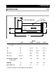
1 OPERATION SPECIFICATIONS 1-2 “B” Fire Port Each Side “A”, Clear Top Opening SIDE VIEW COMPACTOR “D” CONTAINER “C” “E” Model 88SC 30 1/2 x 48 100SC 35 x 60 “B” 70 76 1/8 68 76 1/2 “C” 42 49 5/8 52 1/2 51 1/2 “D” (max.) 96* 104* 104* 104* 254 1/2* 276* 275* 288* Charge Box Capacity (cubic yards) 1.00 1.50 1.90 1.90 WASTEC .70 1.32 1.53 1.53 Cycle Time (sec) 44 37 33 37 “A”, Clear Top Opening (L x W) “E” (max.
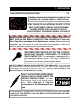
1 OPERATION PRE-OPERATION INSTRUCTIONS 1-3 FEDERAL REGULATION PROHIBITS THE USE OF THIS EQUIPMENT BY ANYONE UNDER 18 YEARS OF AGE. STAY CLEAR OF ALL INTERNAL PARTS OF THE SELF-CONTAINED COMPACTOR/CONTAINER DURING OPERATION. FAILURE TO DO SO COULD RESULT IN SERIOUS INJURY OR DEATH! NEVER ENTER ANY PART OF THE COMPACTOR UNLESS THE DISCONNECT SWITCH HAS BEEN LOCKED-OUT AND TAGGED-OUT. See LockOut & Tag-Out instructions in the Maintenance section. Before starting the compactor, be sure no one is inside.
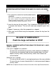
1 OPERATION OPERATOR STATION 1-4 KEYED START SWITCH REVERSE OPERATOR STATION FOR 88SC, 100SC, 250SC, & 250 VL EMERGENCY STOP CONTROL DESCRIPTION FOR 88SC, 100SC, & 250SC 1. KEYED START SWITCH - This switch requires a key for operation. Insert the key and turn clockwise to the start position. Depress and hold the key for one to two seconds and release. The compactor will cycle one time (complete extension and retraction of the ram) and stop.
1 OPERATION OPERATING INSTRUCTIONS FOR RJ-88SC, RJ-100SC, & RJ-250SC 1-5 1. First, place the material to be discarded into the compactor. Note: If you are loading the compactor through a door or gate, close it before starting the compactor. Refer to “Optional Loading Configurations” in the Decal Placement section to determine how your compactor is set up. 2. Insert the key into the key switch. Turn it clockwise and depress for 1 to 2 seconds and release. The unit will make one complete cycle, then stop. 3.
1 OPERATION OPERATING INSTRUCTIONS FOR RJ-250VL 1-6 1. First, place the material to be discarded into the compactor. Note: If you are loading the compactor through a door or gate, close it before starting the compactor. Refer to “Optional Loading Configurations” in the Decal Placement section to determine how your compactor is set up. 2. Insert the key into the key switch. Turn it clockwise and release. The unit will make one complete cycle, then stop. 3.
1 OPERATION OPTIONAL CONTROLS 1-7 1. SUSTAINED MANUAL PRESSURE CONTROL BUTTON (Hold-To-Run, ReleaseTo-Stop) - This option requires the compactor operator to remain at the push button station while the compactor is in use. Actuation requires depressing the "Hold-ToRun" and "Start" buttons. After the unit has started, the "Start" button is released. If the "Hold-To-Run" button is released, the unit will stop instantly. 2.
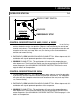
1 OPERATION DECALS for RJ-88SC, RJ-100SC, RJ-250SC, or RJ-250VL 1-8 WARNING DECAL REQUIREMENTS When your compactor leaves the factory, several WARNING DECALS are installed for protection. These labels are subject to wear and abuse due to the nature of the refuse handling operation. THESE DECALS MUST BE MAINTAINED. Additional decals may be purchased from your distributor or from Marathon Equipment Company.
1 OPERATION DECAL PLACEMENT for RJ-88SC, RJ-100SC, RJ-250SC, or RJ-250VL REMOTE POWER UNIT 1-9
1 OPERATION DECAL PLACEMENT for RJ-88SC, RJ-100SC, RJ-250SC, or RJ-250VL 1-10 OPTIONAL LOADING CONFIGURATIONS 06-0039 06-0039 THRU-THE-WALL SECURITY CHUTE DOGHOUSE 06-0039 EACH INSIDE WALL 06-0039 06-0039, 06-0052 DOCK ACCESS GATE & HOPPER 06-0040 EACH OUTSIDE WALL
1 OPERATION ADDITIONAL DECALS and DECAL PLACEMENT for HYDRAULIC TAILGATE (HT) UNITS 1-11 In addition to the decals and their placement specified on the previous pages, the self-contained units with the hydraulic tailgate option require the following decals located as shown below. Decal Number 06-0104 - CAUTION: STAND CLEAR OF TAILGATE WHEN LIFTED. TRUCK MUST BE ON FIRM, LEVEL SURFACE BEFORE LIFTING GATE. FRONT AND REAR HOLD DOWNS MUST BE ENGAGED. TILT HOIST BEFORE LIFTING TAILGATE.
2 MAINTENANCE LOCK-OUT & TAG-OUT INSTRUCTIONS 2-1 FOREWORD: Before entering any part of the compactor, be sure that all sources of energy have been shut off, all potential hazards have been eliminated, and the compactor is locked-out and tagged-out in accordance with OSHA and ANSI requirements. If the ram is pressing against a load, move the ram rearward before shutting the compactor down. The specific lockout and tag-out instructions may vary from company to company (i.e.
2 MAINTENANCE PERIODIC MAINTENANCE 2-2 WARNING: RAM SPEED ACCELERATES AS RAM RETRACTS. NEVER ENTER ANY PART OF THE SELF-CONTAINED COMPACTOR/CONTAINER UNTIL THE UNIT HAS BEEN LOCKED OUT AND TAGGED OUT. MONTHLY 1. Check external hoses for chafing, rubbing, or other deterioration and damage. 2. Check for any obvious unsafe conditions in the compactor area. 3. Check oil level in hydraulic reservoir. Level should be 3/4 of sight gauge. 4. Clean out or wash out debris from behind compactor ram. 5.
2 MAINTENANCE PROCEDURES 2-3 PRESSURE SETTING When the hydraulic cylinders used in the RJ-88SC, RJ-100SC, RJ-250SC, and RJ250VL are fully extended or retracted, they bypass internally. This makes it impossible for the hydraulic system to reach relief pressure. Follow the recommendations below for proper pressure setting. 1. Disconnect and lock out power using the procedure on page 2-1. 2. Using the quick disconnects, disconnect the hydraulic hoses from the compactor. 3.
2 MAINTENANCE PROCEDURES 2-4 RAM CONTROL TIMER ADJUSTMENT Determine the cycle time of your machine. This can be found in the “CHARTS” section of this manual under “TIMER SETTINGS”. Set the timers as shown in the chart. When the switches are properly set, the ram will fully extend, stop for one-half to one second, then fully retract, stop and the unit will shut down. NOTE: As time passes, the cycle time may change and need to be readjusted.
2 MAINTENANCE PROCEDURES 2-5 CYLINDER REMOVAL INSTRUCTIONS 1. Remove access covers from compactor. 2. Remove hoses (4, for 88SC & 250SC, 100SC & 250VL). 3. Remove cylinder pins. 4. Remove cylinders (2, for 88SC & 250SC, 1, for 100SC & 250VL). 5. To install the cylinders, reverse the above steps. MULTI-CYCLE TIMER ADJUSTMENT - OPTION Determine the cycle time of your machine. This can be found in the CHARTS section of this manual under TIMER SETTINGS.
2 MAINTENANCE PRINCIPLES OF OPERATION 2-6 STANDARD SYSTEM OPERATING CHARACTERISTICS, 5 hp & 10 hp The system uses special cylinders to move the ram and two timers to control the operation of the ram. When the hydraulic cylinders used in the RJ-88SC, RJ-100SC, RJ250SC, and RJ-250VL are fully extended or retracted, they bypass internally. This makes it impossible for the hydraulic system to reach relief pressure.
2 MAINTENANCE TAILGATE SEAL REPLACEMENT 2-7 When the door/tailgate seal becomes damaged or worn, replace the seal. WARNING: For units with hydraulic tailgates, before performing any inspection or maintenance on the seal, support the raised tailgate with a crane, forklift, or other positive maintenance prop. l WHEN REMOVING THE OLD SEALS (TOP & BOTTOM), MARK THE POSITION OF THE SEAL JOINTS. PRY THE SEAL RETAINER UP SLIGHTLY TO ALLOW REMOVAL OF THE OLD SEALS.
2 MAINTENANCE CHARTS 2-8 TIMER SETTINGS MODEL NO. RJ-88SC RJ-100SC RJ-250SC RJ-250VL RAM STOP REAR T1 T2 RAM STOP FORWARD T1 T2 27 21 19 21 17 16 13 16 17 16 13 16 27 21 19 21 Includes HT units and SL units. FUSES AND CIRCUIT BREAKERS VAC FULL LOAD AMP. DUAL ELEMENT FUSE MAX. SIZE 5 HP, 1 PH 208 230 22.0 20.8 50 45 80 70 60 60 5 HP, 3 PH 208 230 460 575 13.8 13.4 6.7 5.4 30 25 15 10 40 40 20 15 30 30 30 30 10 HP, 1 PH 208 230 43.0 39.
2 MAINTENANCE CHARTS 2-9 WIRE SIZES THW Copper 75°C (165°F) MOTOR SIZE VOLTAGE LENGTH TO 100’ TO 200’ TO 300’ 5 HP, 1 PH 208 230 8 8 6 6 4 4 5 HP, 3 PH 208 230 460 575 10 10 12 12 6 8 12 12 4 6 10 12 10 HP, 1 PH 208 230 4 4 1 2 1/O 1/O 10 HP, 3 PH 208 230 460 575 6 8 12 12 4 4 10 12 2 3 8 10 MOTOR STARTERS AND HEATER ELEMENTS MOTOR SIZE VOLTAGE STARTER SIZE HEATER ELEMENT A-B JOSLYN CLARK 5 HP, 1 PH 208 230 2 2 W-61 W-60 2452 2451 5 HP, 3 PH 208 230 460 575 1 1 1 1 W-5
2 MAINTENANCE PARTS LIST PART # 02-0050 02-0157 02-0184 02-0197 02-0198 02-0204 02-0214 02-0215 02-0244 02-0267 02-0284 02-0295 02-0305 02-0242 99-7778 02-4037 03-0191 03-0195 03-0196 03-0197 03-0288 03-0345 03-0458 03-0488 03-0927 03-0928 03-0929 03-0936 03-0937 03-1187 04-0210 04-0211 04-0300 04-0301 04-0310 04-0311 04-0330 05-0001 05-0224 05-0247 06-0006 2-10 PART DESCRIPTION 88SC 100SC 250SC 250VL 88HT 250HT SUCTION FILTER X X X X X X DIRECTIONAL VALVE X X X X X X CHECK VALVE X X X X BREATHER X X X X
2 MAINTENANCE MOTOR CONTROL PANEL - TYPICAL 2-11 * * Motor Starter brand and size determined by model number and voltage.
2 MAINTENANCE POWER UNIT - STANDARD 5 HP 2-12 DETAIL B DETAIL B DRAIN PLUG DETAIL A DETAIL A
2 MAINTENANCE POWER UNIT - STANDARD 10 HP 2-13
2 MAINTENANCE HYDRAULIC SCHEMATIC - TYPICAL * SINGLE CYLINDER UNIT SHOWN. FOR DUAL CYLINDER UNITS, CONNECT IDENTICAL CYLINDER IN PARALLEL.
2 MAINTENANCE TROUBLE-SHOOTING CHART 2-15 PROBLEM CAUSE SOLUTION UNIT WILL NOT START ( 1) No electrical power to unit ( 1A) Turn on main disconnect ( 1B) Replace fuses or reset breakers ( 2A) Check primary and secondary sides of transformer ( 2B) Check for correct voltage. Check control fuses.
2 MAINTENANCE TROUBLE-SHOOTING CHART 2-16 PROBLEM CAUSE SOLUTION PUMP MAKES NOISE-SOUNDS LIKE GRAVEL ( 1 ) Partly clogged intake strainer or restricted intake pipe ( 2) Defective bearing ( 3) Air leak at pump intake pipe joints ( 1A) Pump must receive intake fluid freely or cavitation results. Drain system, clean intake pipe and clean or replace strainer ( 2A) Replace pump ( 3A) Tighten joints as required. PUMP SHAFT SEAL LEAKING ( 1) Seal worn or damaged ( 1A) Replace seals or pump.
3 INSTALLATION CONCRETE PAD REQUIREMENTS 3-1 CAUTION: REVIEW THIS MANUAL BEFORE MAKING THE INSTALLATION. STUDY THE JOBSITE AND INSTALLATION REQUIREMENTS CAREFULLY TO BE CERTAIN ALL NECESSARY SAFEGUARDS AND OR SAFETY DEVICES ARE PROVIDED TO PROTECT ALL PERSONNEL AND EQUIPMENT DURING THE INSTALLATION AND AS A COMPLETED SYSTEM. SPECIAL ATTENTION IS DIRECTED TO THE EXTRACT FROM AMERICAN NATIONAL STANDARDS INSTlTUTE Z245.2 .
3 INSTALLATION STEEL INSTALLATION PROCEDURES 3-2 DOCK INSTALLATION If the appropriate accessories are ordered from Marathon Equipment Co., the compactor/container will be furnished with either a four-sided hopper or a three-sided hopper with a hinged gate. THESE ACCESSORIES SHOULD NOT BE ALTERED AS THEY ARE MANUFACTURED IN ACCORDANCE WITH THOSE STANDARDS WHICH PREVAIL AT THE TIME OF MANUFACTURE.
3 INSTALLATION ELECTRICAL & HYDRAULIC INSTALLATION 3-3 The motor control panel contains high voltage components. Only authorized service personnel should be allowed inside. See Lock-Out & Tag-Out instructions in the maintenance section. A lockable fused disconnect switch (customer furnished) must be installed and be within sight of the compactor motor control panel location, not to exceed 50'0" from the compactor.
3 INSTALLATION ELECTRICAL & HYDRAULIC INSTALLATION 3-4 PUSHBUTTON OPERATOR STATION If a remote operator station is furnished, it will be factory wired using Sealtite. If it is necessary to disconnect it from the wires (to install the operator station inside a building), exercise care that these wires are reconnected as originally furnished. (Check local codes to be certain that Sealtite is acceptable.
3 INSTALLATION THROUGH-THE-WALL POWER UNIT INSTALLATION 3-5 If the remote power unit is to be mounted through-the-wall, the following list of material and diagram is the suggested method. List of Material Item No. Quantity 1 2 2 2 3 2 4 2 5 4 6 3 Description Hydraulic Hose, Hi-Pressure (sized to power unit*), 36” long Pipe, Sch 80 (sized to power unit*), 36” long Hydraulic Hose, Hi-Pressure (sized to power unit*), 48” long Steel plate with holes for Item No.
4 HAULER INFORMATION HAULER INSTRUCTIONS - GENERAL 4-1 Before hauling to the landfill: 1. Disconnect all hoses and electrical connections (if applicable) between the power unit and the compactor. Make sure they are laid in an area where they will not get damaged. 2. Close and secure any hopper doors or gates. 3. Make sure that the container door safety chain is secured in the keyhole on the latch side of the container floor. 4.
4 HAULER INFORMATION HAULER INSTRUCTIONS - DOOR/LATCH OPERATION 4-2 CONTAINER DOOR AUTO RELATCH SAFETY CHAIN ALWAYS FASTEN CHAIN IN KEYHOLE WHEN DOOR IS CLOSED. WHEN THE DOOR IS OPEN, SECURE THE CHAIN IN THE KEYHOLE ON THE HINGE SIDE OF THE CONTAINER FLOOR.
4 HAULER INFORMATION HAULER INSTRUCTIONS - HYDRAULIC TAILGATE OPERATION (FOR OPTIONAL HT UNITS) 4-3 The truck hoist must have a hydraulic selector valve with 1500 psi, min. to operate the hydraulic tailgate. The hydraulic tailgate is supplied with one 1/2” NPTF male quick disconnect mounted on the drivers side of the unit. A 1/2” female quick disconnect is supplied for use on the truck hoist valve plumbing. CAUTION * * * * STAND CLEAR OF TAILGATE WHEN LIFTED.
4 HAULER INFORMATION HAULER INSTRUCTIONS - HYDRAULIC TAILGATE OPERATION (FOR OPTIONAL HT UNITS) 4-4 WARNING: NEVER PLACE ANY PART OF YOUR BODY BETWEEN THE TAILGATE AND THE CONTAINER. INSTRUCTIONS FOR USING MAINTENANCE BAR. 1. Lower tailgate approximately 24” between container bottom and compactor tailgate. 2 Remove locking pin from maintenance bar and slide bar toward compactor. 3. Align holes in the position collar and bar and insert pin. 4.
4 HAULER INFORMATION HAULER INSTRUCTIONS - LIQUID REMOVAL (FOR OPTIONAL SL UNITS) 4-5 The Ram Jet Self-Contained Streamline compactor/containers are designed with an internal drain system for liquid removal, ported to each corner of the machine. The unit comes standard with one ball valve. This valve can be moved to any of the four drain outlets on the machine. The valve should be located at the lowest outlet on the machine for proper drainage.