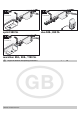
sprint 550 SL duo 500-, 650 SL & marathon 550-, 800-, 1100 SL & Original installation and operating instructions 41040V001-442006-0-OCE-Rev.
Contents General Information . . . . . . . . . . . . . . . . . . . . . . . . . . . . 2 Functions and Connections marathon . . . . . . . . . . . .
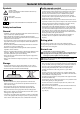
General Information Symbols 1 (1) Radio remote control Caution symbol: Indicates a potential risk. Failure to follow instructions may result in serious injuries. • The radio remote control may only be used for equipment and systems in which defective remote operation of the transmitter or radio receiver does not constitute a risk to people, animals or property, or in cases where this risk is eliminated by means of additional safety facilities. Note symbol: Information, useful advice.
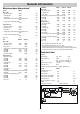
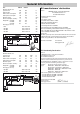
General Information Maximum door dimensions * sprint marathon Max.
General Information duo EU manufacturers’ declaration 500 SL 650 SL Maximum traction and pressure force: 500 650 N Rated traction: 150 195 N Rated current consumption: 0,5 0,7 A Rated power consumption: 110 150 W Maximum speed: 150 180 mm/s Power consumption, stand-by: ~7 ~2 W Weight with: rail 2600: rail 3000: rail 3400: 16,0 17,4 18,4 16,0 17,4 18,4 kg kg kg Messrs.
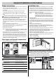
Preparations for Installation Safety instructions Personal protective equipment • The power cable supplied as standard may be neither shortened nor lengthened. • The voltage of the power source must correspond to that indicated on the drive's rating plate. • All devices requiring external connection must be equipped with safe contact separation as per IEC 364-4-41 to isolate them from the mains voltage supply. • Live parts of the drive (voltage-carrying parts e.g.
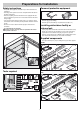
Preparations for Installation marathon 10 4 1 3 Rev. E 6 5 12 9 t n ri sp 0 55 0 , 55 S L S n o h at ar m o u d D 00 , 11 0, 80 055 on ge un d 0 , 65 S ta 0 50 M et L S L S B rie sa bs nl ei tu ng 2. 3. 4. 5. 6. 7. 8. 9. 10. 11. 12. 13. 30 - 3 - Item 1.
General Installation Information Safety instructions Installation tips • Installation, connection and initial operation of the drive mechanism may only be carried out by qualified specialists. • Check that all the parts have been supplied before you start installation work in order to save time and unnecessary work if a part is missing. • Do not operate the door when people, animals or objects are in its area of movement. • Installation work can be carried out quickly and reliably by two persons.
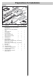
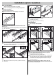
Installation sprint / marathon Pre-installation 5 6 1 • Remove the drive mechanism from its packaging. Dispose of packaging material according to the applicable statutory regulations. 2 Caution for sprint and duo! The plastic chain case is not packaging – do not remove! 3 1 1 2 5 • Unscrew two steel angle irons with length adjustment holes (1) and screw onto ceiling bracket (2) as shown. 6 • Dismantle drive shaft (1): Pull out clip fixing (2) and remove bolt (3).
Installation sprint / marathon 8 Caution! Mount the drive in parallel to the runner rails of the door. VM 9 D S ½ 30 15 ½ 15 30 min.15 For installation on the ceiling (D), drill holes at distances of 15 mm, if possible. Smaller angle of inclination of the fixing brackets. HM 13 8 • The drive mechanism can be mounted on lintel (S) or ceiling (D). 9 • Measure front centre point (VM) of door and mark on door and on lintel or ceiling. 10 • Align ceiling bracket (1).
Montage sprint / marathon Installing the socket outlet 4 17 4 2 Socket may only be installed by a qualified electrician. Protect socket with a fuse (16 A slow-blow type). 1 5 6 Observe all applicable regulations (e.g. VDE, etc.)! ca N ca 19 .0 3 .0 ,5m 1 max. 30° ,5m 1 Trim (e.g. saw off and debur) projecting part of ceiling bracket (4). 3 17 • Release rear cut-off buffer (1) and push right back to stop (2). Open door (3) by hand.
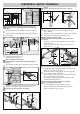
Installation duo Selection of installation option 3 Select the desired installation option. For option (B), change the position of power supply unit. 1 1 4 2 Caution for sprint and duo! The plastic chain case is not packaging - do not remove! B 2 1 3 • Push bogie truck (1) onto C-rail (2). 4 • Slot two C-rails (1) into connecting element (2) and push together as far as they will go.
Installation duo 8 3 1 1 4 2 2 1 9 3 • Push trolley (1) onto C-rail (2). 4 • Slot two C-rails (1) into connecting element (2) and push together as far as they will go. 10 1 17mm 17mm V 5 a 5 4 1 2 3 2 1 b 90 ° 4 3 c 2 9 10 • Push ceiling suspension fitting (1) onto C-rail (2). 6 • Mount bracket (2) with screw (1) and nut (3) onto the connecting element (4). 5 Pre-assembly for installation option B Dispose of the packaging correctly in accordance with local requirements.
Installation duo 9 10 12 1 17mm 17mm VM 13 D S V 4 15 3 2 30 2 • Push ceiling suspension fitting (1) onto C-rail (2). 10 15 30 1 9 min.15 For installation on the ceiling (D), drill holes at distances of 15 mm, if possible. Smaller angle of inclination of the fixing brackets. • Mount bracket (2) with screw (1) and nut (3) onto the connecting element (4).
Installation duo Caution! Mount the drive in parallel to the runner rails of the door. Trim (e.g. saw off and debur) projecting part of ceiling bracket (4). • Push cut-off buffer (1) right up to end stop (6) against bogie unit (5), until it clicks. Securely tighten screw on switch-trigger (1). Installing and connecting the control unit Selection of the installation option Position the push-button in such a way that the operator can see the door, while he/she is not inside the operating area of the door.
Installation duo Installation option A/B 28 A 23 29 3 4 B 23 2 2 2 1 1 3 1,6m 6 3 4 5 3 1 2 DIP ON 4 4 1,6m °,1 `m 6 4 3 2 °,1 `m 6 4 3 2 7 8 3 4 5 1 6 Installation option C 23 24 1 H 2 3 4x ca 150 4 3 • Choose a suitable location for the installation of the control housing (1), preferably near a power socket (3).
Installation duo 27 28 Installing and connecting and additional push-button 3 4 2 Only necessary if a further push-button is required in addition to the one already installed (1). 1 4 5 6 Use the contact only for potential-free normally closed contacts. External voltage may damage or even destroy the control unit. 3 3 2 DIP 1 4x ON 1 2 3 4 5 6 7 8 5 6 34 2 1 12 27 • Position, align and the secure control housing using 4 screws (1). Supplied components 2 plugs, 2 screws.
Installation duo 17
Commissioning Safety Instructions Teaching in drive Once the drive has been installed, the person responsible for installation has to issue an EU Conformity Declaration for the door system in accordance with Machine Directive 98/37/EG as well as fitting the CE seal and the rating plate. This also applies to doors installed for private purposes and in cases where the drive has been retrofitted to a manual door.
Commissioning Checking emergency release Continue with programming the other hand-held transmitters. To do this, repeat the above steps. The maximum number of memory blocks is 112 per radio receiver. With sectional doors, or doors with ceiling guides, you have the option of activating the backjump with DIP switch 6 in order to offload the operator and door mechanisms. Attaching instruction label 1 46502V000-172006-0-OCE_Rev.A 46502V000-172006-0-OCE_Rev.
Operation and Handling Safety Instructions • Keep children, disabled persons and animals away from the door. • Keep your hands clear of a door in operation and any moving parts. • Only drive into and out of the garage when the door is fully opened. • Risk of persons trapping or cutting themselves in/on the door system's moving parts or edges where it closes. N N Opening door 1 • Pull once on emergency release wire (N): the drive mechanism disengages and the door can be opened manually.
Operation and Handling Interim stop Description of display and push-buttons If an interim stop occurs due to the operation of a push-button or the manual remote control, the drive unit stops immediately. The next command given sends the drive in the opposite direction. See 'Pulse Sequence of Door Movement' section. Safety stop 1 (automatic force cut-off) 6 2 5 4 4 3.2 8 1 7 When the automatic force cut-off is activated, the drive stops or reverses.
Operation and Handling Deleting a channel from the radio receiver • Press setting button (1) and keep pressed - press 1x for channel 1; LED (3.1) lights up - press 2x for channel 2; LED (3.2) lights up - The LED that lights up depends on which channel has been selected. After 5 seconds, the LED starts to flash and then remains lit after a further 10 seconds.
Functions and Connections marathon General tips Backjump (DIP 6) DIP switch In vertical-sectional doors, you have the option of activating the backjump with DIP switch 6 in order to offload the operator system and the door. It also facilitates the activation of the emergency release. • Depending on the position (OFF or ON) of a DIP switch, a number of additional functions can be activated or deactivated. By default, all DIP switches are -> OFF.
Functions and Connections marathon Automatic close mode (DIP 4) Automatic close mode + light barrier, option 2 Interrupt automatic closing manually by installing switch in the light barrier's supply cable. Observe standard EN 12453 (e.g. fit light barrier 1) for automatic close mode. An additional light barrier can be connected to safety connection 2 as upper safety limit. As described above, apart from the fact that the drive mechanism closes the door 5 seconds after the light barrier has been crossed.
Functions and Connections marathon Trolley board Connecting light barrier 1 Supplied as standard with jumper. 6 4 2 6 1 4 M550-800 3 8 5 3 8 5 7 1 2 M1000 Terminals 6 + 7 7 tested connection for floating contacts, only if DIP switch 2 is OFF Terminals 10 + 11 regulated 24 V/DC, max. 0.
Functions and Connections marathon Chain and C-rail 12 Volt connection Supplied connected as standard. 8 Terminal 12 Chain Terminal 13 C-rail 9 10 12 11 13 14 15 16 17 18 19 Supplied vacant as standard. 2 16 Terminal 19 Torminal 21: Earth Floating relay output Supplied vacant as standard. 9 10 12 11 13 14 15 16 17 18 19 Supplied vacant as standard.
Functions and Connections marathon TorMinal interface Special functions See TorMinal Operating Instructions. 'Dead man' mode Door status indicator T2 Maintenance monitoring T1 Only TorMinal can be used for this and other functions or settings. For details regarding the special functions, please refer to your TorMinal operating manual. D4 Connecting Fraba system The integrated evaluation of the Fraba system can only be switched on through the TorMinal system.
Functions and Connections sprint / duo General tips Connecting warning lamp (DIP 4) • DIP switch in OFF position as standard when supplied. • Permissible cable cross-section: max. 1,5 mm².
(“k’ƒmjñòóôõö÷øùúûüýþÿÑÒÓÔÕÖ×ØÙÚÜÝÞßàáâãäåæçèéêë쨩ª«¬−®°̄±²³́µ¶·¹̧º»¼½¾¿ÀÁÂÃÄÅÆÇÈÉÊËÌ”•–—˜™š›œŸ¡¢£¤¥¦„…†‡ˆ‰Š‹Œ‘~‚vwxyz{|nopqrstlhi_àbcdefKLMNOPQRSTUVWXYZ[=>?@ABCDEFGHI123456789:.)*+,#$%&'`˘˙˚˝˛ı̌§}íÍug\J;/-îÎ]<0!ïÏ^"ðÐ 8 End switch gate OPEN 5 Motor cable 6 Motor cable 7+8 End switch gate CLOSED (“k’ƒmjñòóôõö÷øùúûüýþÿÑÒÓÔÕÖ×ØÙÚÜÝÞßàáâãäåæçèéêë쨩ª«¬−®°̄±²³́µ¶·¹̧º»¼½¾¿ÀÁÂÃÄÅÆÇÈÉÊËÌ”•–—˜™š›œŸ¡¢£¤¥¦„…†‡ˆ‰Š‹Œ‘~‚vwxyz{|nopqrstlhi_àbcdefKLMNOPQRSTUVWXYZ[=>?@ABCDEFGHI123456789:.
Miscellaneous Maintenance and Care Disassembly Important information Observe safety instructions! Never use a hose or a high-pressure cleaner to spray down the drive or the control unit housing. The sequence of operations is identical to that described in the Section entitled "Installation" but in reverse order. The setting procedures described are not applicable. • Always disconnect the mains plug prior to working on the drive mechanism. • Never use lyes or acids for cleaning purposes.
Maintenance and Care Changing bulb sprint / marathon Changing fuses marathon • Disconnect plug from socket. • Disconnect plug from socket. A/B/C 3 3 3 od C 2 e 2 2 1 • Remove light diffuser (2). • Remove control unit lid (1). Remove screws (2). • Turn bulb (3) anticlockwise and remove. • Pull out control unit (3). • Fit new bulb (32,5 Volt, 34 Watt, BA 15s or 24 Volt, 21 Watt, BA 15s) and turn clockwise until it locks into position.
Maintenance and Care Regular checks Check safety devices regularly, every year at the very least, to ensure they function correctly (e.g. BGR 232). Safety devices that are sensitive to pressure (e.g. safety switch unit) should be checked every four weeks to ensure they function correctly; see pr EN 60335-2-95.
Troubleshooting Further troubleshooting tips Homelink compatible! If your vehicle is equipped with the latest Homelink system (version 7), you can reach our drive/radio receiver at 868.6 MHz. With older Homelink versions, use other radio frequencies (40.685 or 434.42 MHz). For more details, visit www.eurohomelink.com or contact your local stockist.
Troubleshooting Fault Operator does not close door Possible cause Remedial action Power supply to photoelectric cell interrupted. Check connection replace fuse Power supply to drive interrupted The first command issued after restoration of the mains supply results in the drive opening the gate fully. Drive opens gate but then no further reaction Safety input tripped - Remove obstacle from light barrier to a command given via push-button or (e.g.