® DCM100 DC Monitor User’s Manual Revision 1.0 Copyright © 2008 Maretron, LLP All Rights Reserved Maretron, LLP 9014 N. 23rd Ave #10 Phoenix, AZ 85021-7850 http://www.maretron.com Maretron Manual Part #: M000026 Revision 1.
DCM100 User’s Manual Revision History Revision 1.0 Original document Page ii Description Revision 1.
® Table of Contents 1 Introduction ...........................................................................................................................1 1.1 Firmware Revision .................................................................................................... 1 1.2 DCM100 Features .................................................................................................... 1 1.3 Quick Install .....................................................................................
DCM100 User’s Manual 4.3 4.4 4.5 4.6 5 6 7 8 9 10 11 Battery Capacity ..................................................................................................... 10 Battery Types ......................................................................................................... 10 Battery Safety Precautions ..................................................................................... 11 Charging Inefficiencies ........................................................................
® 1 Introduction Congratulations on your purchase of the Maretron DC Monitor (DCM100). Maretron has designed and built your DC monitor to the highest standards for years of dependable and accurate service.
DCM100 User’s Manual 2 Installation 2.1 Unpacking the Box When unpacking the box containing the Maretron DCM100, you should find the following items: 1 – DCM100 – DC Monitor 1 – DC Current Sensor with 5 ft. long cable (Part # LEMHTA200-S) (outer cable covering grey) 1 – Battery Temperature Sensor with 5 ft. long cable (Part # TR3K) (outer cable covering grey) 1 – Battery Voltage Sense Cable, 5 ft. long (Part # FC01) (outer cable covering white ) 1 – Power Cable, 5 ft.
® 2.3 Mounting the DCM100 Attach the DCM100 securely to the vessel using the included stainless steel mounting screws or other fasteners as shown in Figure 1 below. Figure 1 – Mounting the DCM100 2.4 Connecting the DCM100 The DCM100 requires two electrical connections as shown in . Refer to Section 2.4.1 for making the NMEA 2000® connection and Section 2.4.2 for making the DC monitor connections (i.e., current sensor, sensing voltage, and temperature sensor connections).. 2.4.
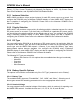
DCM100 User’s Manual Figure 2 – NMEA 2000® Connector Face Views 2.4.2 Connecting the DC power and Sensor Connections The DCM100’s DC Power and sensor connections are made by connecting to the 12-pin terminal strip on the top of the unit. First, remove the four screws at the corners of the unit securing the splash guard to the unit. On the bottom of the splash guard, you will find a label detailing the wire connection to pin number assignments, which are repeated in the table below.
® e. Disconnect the wire from the positive terminal of the battery or other DC source that is being monitored and place it through the hole in the Current Sensor such that the arrow on the Current Sensor points towards the battery or DC source. Then, reattach the wire to the positive terminal of the battery or other DC source. Step 2: The temperature sensor (TR3K) has a gray cable containing red and black wires. Connect the Temperature Sensor as follows: a.
DCM100 User’s Manual Period, 17) Zero Current Threshold, 18) Manually Set Battery to 100%, 19) Current Sensor Zero Offset Calibration, and 20) NMEA 2000 PGN Enable/Disable. 2.5.1 Instance Selection NMEA 2000® provides a unique engine instance for each DC power source on a vessel. You configure the DCM100 using a Maretron DSM250 display or other NMEA 2000® display unit that is capable of configuring the DCM100. Please refer to the Maretron DSM250 User’s Manual for details. 2.5.
® 2.5.4.3 Equalization You may indicate here whether or not the battery supports equalization. This is used only for reporting over the NMEA 2000 network. Available choices are “Supported” and “Not Supported”. 2.5.4.4 Temperature Coefficient The capacity of a battery generally increases with increasing temperature.
DCM100 User’s Manual available, you can set this parameter to the estimated battery temperature, between -25°C and 125°C. 2.5.4.11 Time Remaining Floor The DCM100 calculates the time, given the current being discharged from the battery, before the battery becomes discharged. By default, the DCM100 considers a battery to be discharged when its state of charge reaches the “Time Remaining Floor” value, which is by default set to 50%.
® 3.1 Parameters Common to DC Sources and Batteries The parameters in this section are transmitted regardless of the “DC Type” selected (see Section 2.5.3 for details). 3.1.1 Battery Voltage This parameter indicates the voltage present across the battery terminals. 3.1.2 Battery Current This parameter indicates the voltage being supplied to the battery, in the case of charging, or being supplied from the battery, in the case of discharging.
DCM100 User’s Manual 4 Background 4.1 Why Monitor Batteries? The lifetime and storage capacity of batteries can be greatly affected by the way in which they are used. Discharging a battery excessively or under-charging or over-charging a battery can ruin it. A battery monitor can help you monitor and adjust your battery usage to extend a battery’s lifetime to the maximum possible.
® 4.5 Battery Safety Precautions 1. Lead-acid batteries generate explosive gases during operation. Make sure that the area around the batteries is well-ventilated. Never allow flames or sparks near a battery. 2. Wear clothing and eye protection when working with batteries. If battery acid comes into contact with your skin or clothing, wash them immediately with soap and water.
DCM100 User’s Manual restated version of the equation, which allows you to calculate the time to totally discharge a given battery at a given discharge current, follows: ܶ ൌ ܴቀ ቁ , where ூோ = ܥthe rated battery capacity in Amp-hours, ܴ = the number of hours over which the rated battery capacity was calculated (usually 20), = ܫthe discharge current in Amperes, ܶ = the time to discharge the battery in hours, and ݊ = the Peukert constant for the battery (dimensionless).
® • • • • Clean the unit with a soft cloth. Do not use chemical cleaners as they may remove paint or markings or may corrode the DCM100 enclosure or seals. Ensure that the unit is mounted securely and cannot be moved relative to the mounting surface. If the unit is loose, tighten the mounting screws. Check the security of the cable connected to the NMEA 2000® connector, and tighten if necessary.
DCM100 User’s Manual automatically void the warranty. If service is required, please return the unit to an authorized Maretron service location. 8 Technical Specifications As Maretron is constantly improving its products, all specifications are subject to change without notice. Maretron products are designed to be accurate and reliable; however, they should be used only as aids to navigation and not as a replacement for traditional navigation aids and techniques.
® Environmental Parameter IEC 60954 Classification Degree of Protection Operating Temperature Storage Temperature Relative Humidity Vibration Rain and Spray Solar Radiation Corrosion (Salt Mist) Electromagnetic Emission Electromagnetic Immunity Safety Precautions Value Exposed IP64 -25°C to 55°C -40°C to 70°C 93%RH @40° per IEC60945-8.2 2-13.2Hz @ ±1mm, 13.2-100Hz @ 7m/s2 per IEC 60945-8.7 12.5mm Nozzle @ 100liters/min from 3m for 30min per IEC 60945-8.
DCM100 User’s Manual 10 Installation Template Please check the dimensions before using the following diagram as a template for drilling the mounting holes because the printing process may have distorted the dimensions. Figure 3 – Mounting Surface Template Page 16 Revision 1.
® 11 Maretron (2 Year) Limited Warranty Maretron warrants the DCM100 to be free from defects in materials and workmanship for two (2) years from the date of original purchase. If within the applicable period any such products shall be proved to Maretron’s satisfaction to fail to meet the above limited warranty, such products shall be repaired or replaced at Maretron’s option.
® Appendix A – NMEA 2000® Interfacing DCM100 NMEA 2000® Periodic Data Transmitted PGNs PGN 127506 – DC Detailed Status The DCM100 uses this PGN to transmit slowly changing DC and Battery Data Field 1: 2: 3: 4: 5: 6: 7: SID – The sequence identifier field is used to tie related PGNs together. For example, the DCM100 will transmit identical SIDs for 127506 (DC Detailed Status) and 127508 (Battery Status) to indicate that the readings are linked together (i.e.
DCM100 User’s Manual PGN 127508 – Battery Configuration Status The DCM100 uses this PGN to transmit unchanging battery configuration data. Field 1: Battery Instance – This field indicates the particular battery for which this data applies. A single battery will have an instance of 0. Batteries in boats with multiple batteries will be numbered uniquely, starting at 0. 2: Battery Type – This field indicates the type of battery. The DCM100 indicates one of the following values: 0=Flooded, 1=Gel, 2=AGM.