® RAA100 Rudder Angle Adapter User’s Manual Revision 1.0 Copyright © 2006 Maretron, LLC All Rights Reserved Maretron, LLC 9034 N. 23rd Ave #13 Phoenix, AZ 85021-7850 http://www.maretron.com Maretron Manual Part #: M001101 Revision 1.
RAA100 User’s Manual Revision History Revision 1.0 Original document Page ii Description Revision 1.
® Table of Contents 1 2 3 4 5 6 7 8 General ................................................................................................................................1 1.1 Introduction ....................................................................................................................1 1.2 Firmware Revision .........................................................................................................1 1.3 Features ........................................................
RAA100 User’s Manual Table of Figures Figure 1– Mounting Location When Used with Analog Gauge .................................................. 3 Figure 2 – Mounting Location When Used Without Analog Gauge............................................ 4 Figure 3 – RAA100 Connections ............................................................................................... 4 Figure 4 – NMEA 2000® Connector Face Views .......................................................................
® 1 General 1.1 Introduction Congratulations on your purchase of the Maretron Rudder Angle Adapter (RAA100). Maretron has designed and built your adapter to the highest standards for years of reliable, dependable, and accurate service. The RAA100 is used to adapt commercially available rudder angle senders to the NMEA 2000® network. This allows you to observe the rudder angle anywhere on the vessel where there is an NMEA 2000® compatible display such as the Maretron DSM200.
RAA100 User’s Manual 4. 5. 6. 7. Configure or Program the Rudder Instance Number (Section 3.1) Configure or Program the Operating Mode (Section 3.2) Configure or Program the Resistive Sender type: American or European (Section 3.3.1) Optional – Custom Calibration (Section 3.3.2) 2 Installation 2.1 Unpacking the Box When unpacking the box containing the Maretron RAA100, you should find the following items.
® Figure 1– Mounting Location When Used with Analog Gauge 2.2.2 Mounting Location When Used Without Analog Gauge(s) The RAA100 has two primary connections: 1) the NMEA 2000® network connection, and 2) the resistive rudder angle sender connection. Therefore, the RAA100 should be located between the NMEA 2000® trunk line and the resistive rudder angle sender.
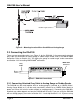
RAA100 User’s Manual Rudder Angle Sensor Figure 2 – Mounting Location When Used Without Analog Gauge 2.3 Connecting the RAA100 There are two connection points (see Figure 3) for the RAA100: 1) the permanently attached gray cable for connection to analog gauge or rudder angle sender, and 2) the NMEA 2000® connection. Refer to Section 2.3.1 for making the gauge or rudder angle sender connection and Section 2.3.2 for making NMEA 2000® connection.
® the RAA100 as a stand-alone adapter without attaching an analog gauge, then skip Section 2.3.1.1 and refer to Section 2.3.1.2. 2.3.1.1 Connecting Attached Gray Cable to Analog Gauge Connecting the RAA100’s permanently attached gray cable to the analog gauge does not require the removal of any wires between the gauge and the rudder angle sender.
RAA100 User’s Manual end of the cable to the RAA100 (note the key on the male connector and keyway on the female connector). Be sure the cable is connected securely and that the collar on the cable connector is tightened firmly. Connect the other end of the cable (male) to the NMEA 2000® network in the same manner. The RAA100 is designed such that you can plug or unplug it from an NMEA 2000® network while the power to the network is connected or disconnected.
® 3.2 Configuring Operating Mode The RAA100 operates in one of two modes: 1) NMEA 2000® Mode, or 2) NMEA 2000® / Analog Gauge Mode. You configure or place the RAA100 into NMEA 2000® Mode when you are connecting the RAA100 directly to the resistive rudder angle sender (see Figure 2) and you are not using an analog gauge.
RAA100 User’s Manual terminal are between 100 and 400 ohms, however, some gauges have very high resistance (i.e., greater than 3000 ohms). A resistance value over 3000 ohms generally indicates a low cost, low accuracy gauge (i.e., gauge reading changes with battery voltage even though the rudder angle is not changing). If the resistance measurement is above 3000 ohms, don’t worry about recording the exact reading, as the maximum programmable value in the RAA100 is 3000 ohms.
® 5 Troubleshooting If you notice unexpected operation of the Maretron RAA100, follow the troubleshooting procedures in this section to remedy simple problems. Symptom Troubleshooting Procedure No rudder angle 1. If operating in the NMEA 2000® Mode, check the connections to the output NMEA 2000® interface (see Section 2.3.2) and/or the connection to the resistive rudder angle sender (see Section 2.3.1.2) and tighten if necessary. 2.
RAA100 User’s Manual Figure 5 – Troubleshooting Guide If these steps do not solve your problem, please contact Maretron Technical Support (refer to Section 7 for contact information).
® Environmental Parameter IEC 60954 Classification Degree of Protection Operating Temperature Storage Temperature Relative Humidity Vibration Rain and Spray Solar Radiation Corrosion (Salt Mist) Electromagnet Emission Electromagnetic Immunity Safety Precautions Value Exposed IP67 -25°C to 55°C -40°C to 70°C 93%RH @40° per IEC60945-8.2 2-13.2Hz @ ±1mm, 13.2-100Hz @ 7m/s2 per IEC 60945-8.7 12.5mm Nozzle @ 100liters/min from 3m for 30min per IEC 60945-8.
RAA100 User’s Manual 8 Maretron (2 Year) Limited Warranty Maretron warrants the RAA100 to be free from defects in materials and workmanship for two (2) years from the date of original purchase. If within the applicable period any such products shall be proved to Maretron’s satisfaction to fail to meet the above limited warranty, such products shall be repaired or replaced at Maretron’s option.
® Appendix A – NMEA 2000® Interfacing RAA100 NMEA 2000® Periodic Data Transmitted PGNs PGN 127245 – Rudder The RAA100 uses this PGN to indicate the attached rudder instance and rudder angle. Field 1: Rudder Instance – This field is used to identify the rudder instance number and ranges between 0 and 251. 2: Direction Order – This field identifies a directional command contained in this message.