® NBE100 Network Bus Extender User’s Manual Revision 1.0 Copyright ©2011 Maretron, LLP All Rights Reserved Maretron, LLP 9014 N. 23rd Ave #10 Phoenix, AZ 85021-7850 http://www.maretron.com Maretron Manual Part #: M003006 Revision 1.
NBE100 User's Manual Revision History Revision 1.0 Original document Page ii Description Revision 1.
® Table of Contents 1 Introduction ...........................................................................................................................1 1.1 Firmware Revision .................................................................................................... 1 1.2 NBE100 Features ..................................................................................................... 1 1.3 NBE100 Accessories ...............................................................................
NBE100 User's Manual This page intentionally left blank Page iv Revision 1.
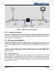
® 1 Introduction Congratulations on your purchase of the Maretron Network Bus Extender. Maretron has designed and built your NBE100 to the highest standards for years of dependable and accurate service. Maretron's NBE100 (Network Bus Extender) allows you to extend the maximum node count, network trunk length and cumulative drop length of any NMEA 2000® network. The NBE100 solves bus errors and other electrical issues caused by exceeding any of these limitations and makes design of large networks easier.
NBE100 User's Manual 1.4 Quick Install Installing the Maretron NBE100 involves the following five steps. Please refer to the individual sections for additional details. 1. 2. 3. 4. Unpack the box (Section 2.1) Choose a mounting location (Section 2.2) Mount the NBE100 (Section 2.3) Connect the NBE100 (Section 2.4) 2 Installation 2.
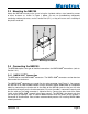
® 2.3 Mounting the NBE100 Attach the NBE100 securely to the vessel using the included stainless steel mounting screws or other fasteners as shown in Figure 1 below. Do not use threadlocking compounds containing methacrylate ester, such as Loctite Red (271), as they will cause stress cracking of the plastic enclosure. Figure 1 – Mounting the NBE100 2.4 Connecting the NBE100 The NBE100 requires one type of electrical connection: the NMEA 2000® connections (refer to Section 2.4.1). 2.4.
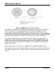
NBE100 User's Manual Figure 2 – NMEA 2000® Connector Face Views The NBE100 is installed on an NMEA 2000® network between the two sections that you wish to physically isolate. There is no electrical connection through the NBE100, so you must ensure that each of the two NMEA 2000® networks connected to the NBE100 must have separate power sources and two termination resistors.
® Figure 3 – NBE100 Connection Diagram 2.4.2 Checking Connections Once the NMEA 2000® connections to the NBE100 have been completed, check to see that information is being properly transmitted by using an appropriate NMEA 2000® display to observe a sensor on the opposite side of the NBE100. If you don’t see data from that sensor, refer to Section 4, “Troubleshooting”. 2.
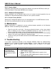
NBE100 User's Manual 2.5.2 Device Label Program this parameter with a text string which identifies this particular NBE100, to allow you to easily distinguish it from other NBE100’s on the network. 2.5.3 Advanced Configuration… Certain parameters do not normally need to be set in order for normal operation, but are included in an advanced configuration section for use in special situations. 2.5.3.
® 5 Technical Specifications As Maretron is constantly improving its products, all specifications are subject to change without notice. Maretron products are designed to be accurate and reliable; however, they should be used only as aids to navigation and not as a replacement for traditional navigation aids and techniques.
NBE100 User's Manual Environmental Parameter IEC 60945 Classification Degree of Protection Operating Temperature Storage Temperature Relative Humidity Vibration Rain and Spray Solar Radiation Corrosion (Salt Mist) Electromagnetic Emission Electromagnetic Immunity Safety Precautions Value Exposed IP67 -25°C to 55°C -40°C to 70°C 93%RH @40° per IEC60945-8.2 2-13.2Hz @ ±1mm, 13.2-100Hz @ 7m/s2 per IEC 60945-8.7 12.5mm Nozzle @ 100liters/min from 3m for 30min per IEC 60945-8.
® 7 Installation Template Please check the dimensions before using the following diagram as a template for drilling the mounting holes because the printing process may have distorted the dimensions. Figure 4 – Mounting Surface Template Revision 1.
NBE100 User's Manual 8 Maretron (2 Year) Limited Warranty Maretron warrants the NBE100 to be free from defects in materials and workmanship for two (2) years from the date of original purchase. If within the applicable period any such products shall be proved to Maretron’s satisfaction to fail to meet the above limited warranty, such products shall be repaired or replaced at Maretron’s option.