® SIM100 Switch Indicator Module User’s Manual Revision 1.0 Copyright © 2008 Maretron, LLP All Rights Reserved Maretron, LLP 9014 N. 23rd Ave #10 Phoenix, AZ 85021-7850 http://www.maretron.com Maretron Manual Part #: M001801 Revision 1.
SIM100 User's Manual Revision History Revision 1.0 Original document Page ii Description Revision 1.
® Table of Contents 1 Introduction ...........................................................................................................................1 1.1 Firmware Revision .................................................................................................... 1 1.2 SIM100 Features ...................................................................................................... 1 1.3 Quick Install ...................................................................................
® 1 Introduction Congratulations on your purchase of the Maretron Switch Indicator Module. Maretron has designed and built your SIM100 to the highest standards for years of dependable and accurate service. Maretron’s Switch Indicator Module monitors switch closure devices including, but not limited to, safety equipment (e.g., heat, smoke, carbon monoxide, explosive vapor detectors), security systems (e.g.
SIM100 User's Manual 1.
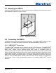
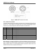
® 2.3 Mounting the SIM100 Attach the SIM100 securely to the vessel using the included stainless steel mounting screws or other fasteners as shown in Figure 1 below. Figure 1 – Mounting the SIM100 2.4 Connecting the SIM100 The SIM100 requires two types of electrical connections: 1) the NMEA 2000® connection (refer to Section 2.4.1), and 2) the switch connections, which are described in Section 2.4.2. 2.4.1 NMEA 2000® Connection The NMEA 2000® connector can be found on the side of the enclosure.
SIM100 User's Manual Figure 2 – NMEA 2000® Connector Face Views 2.4.2 Switch Connections The SIM100 switch connections are made by connecting to the 12-pin terminal strip on the top of the unit. First, remove the four screws at the corners of the unit detaching the splash guard from the unit. On the bottom of the splash guard, you will find a label detailing the wire connection to pin number assignments, which are repeated in the table below.
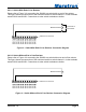
® 2.4.2.1 Switch With End of Line Resistor Please refer to Figure 3 for connecting the SIM100 to a switch with an end of line resistor. This figure shows the connection of the monitored switch to switch channel 1 via the terminals named SW1A and SW1B. Connections to other switch terminals are similar.
SIM100 User's Manual 2.4.3 Checking Connections Once the NMEA 2000® connection and switch connection(s) to the SIM100 have been completed, check to see that information is being properly transmitted by observing an appropriate NMEA 2000® display. If you don’t see switch indicator status, refer to Section 5, “Troubleshooting”. 2.
® 2.5.8 Advanced Configuration… Certain parameters do not normally need to be set in order for normal operation, but are included in an advanced configuration section for use in special situations. 2.5.9 NMEA 2000® PGN Enable/Disable The SIM100 is capable of transmitting NMEA 2000® messages (or PGNs) associated with monitored switch circuits. You may individually enable or disable each of these messages. You may also change the rate of transmission of each of these messages if desired. 2.5.
SIM100 User's Manual A switch indicator always reads “Closed” A switch indicator always reads “Error” A switch indicator always reads “Open” Page 8 Ensure that there is not a short circuit in the wiring for the switch. Measure the resistance between the “A” and “B” terminals for the appropriate indicator.
® 5 Technical Specifications As Maretron is constantly improving its products, all specifications are subject to change without notice. Maretron products are designed to be accurate and reliable; however, they should be used only as aids to navigation and not as a replacement for traditional navigation aids and techniques.
SIM100 User's Manual 6 Technical Support If you require technical support for Maretron products, you can reach us in any of the following ways: Telephone: Fax: E-mail: World Wide Web: Mail: Page 10 1-866-550-9100 1-602-861-1777 support@maretron.com http://www.maretron.com Maretron, LLC Attn: Technical Support 9014 N. 23rd Ave Suite 10 Phoenix, AZ 85021 USA Revision 1.
® 7 Installation Template Please check the dimensions before using the following diagram as a template for drilling the mounting holes because the printing process may have distorted the dimensions. Figure 5 – Mounting Surface Template Revision 1.
SIM100 User's Manual 8 Maretron (2 Year) Limited Warranty Maretron warrants the SIM100 to be free from defects in materials and workmanship for two (2) years from the date of original purchase. If within the applicable period any such products shall be proved to Maretron’s satisfaction to fail to meet the above limited warranty, such products shall be repaired or replaced at Maretron’s option.
® Appendix A – NMEA 2000® Interfacing SIM100 NMEA 2000® Periodic Data Transmitted PGNs PGN 127501 – Binary Switch Bank Status The SIM100 uses this PGN to transmit the state of each of the connected switch inputs Field 1: Indicator Bank Instance – This field identifies the particular switch bank to which this PGN applies. Please refer to Section 2.5.1 for instructions on how to program the value of this field.