
Owner`s manual


23
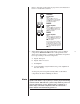
Refer to the table on the previous page and to the illustration
below for additional assistance.
control
Nº320S
Preamplifier
Step A:
Connect the (or slave out)
communication port on the preamplifier
to the input communication port
on the first power amplifier.
Nº432
Power Amplifier
Step B:
Connect the control communicatio
port on the first power amplifier to the
input communication port on the
second power amplifier.
Nº431
Power Amplifier
Step C:
Connect the control communicatio
port on the second power amplifier to th
input communication port on the
third power amplifier.
This step can be repeated to include up
six power amplifiers in the slave chain. I
no additional power amplifiers are includ
in the slave chain, the last power amplifi
control communication port is not
connected.
input
controlinput
3. When Link connections have been made, power on linked
components ONE AT A TIME in the order specified below.
Allow each component to complete its initialization sequence
before proceeding to the next component.
A. Digital Transports
B. Digital Audio Processors
C. Preamplifier
D. Power Amplifiers (begin with the first power amplifier in
the slave chain)
At this point, the front panel standby LEDs on all linked
components should be blinking in unison.
Note Linked components must be powered on ONE AT A TIME in the
specific order listed in step 3 (above) to ensure proper functioning
of Link controls. DO NOT use a power strip switch to power on
several components at once. When power is supplied to a
power strip, connected components that do not include a
power button will automatically power on.