
Owner's Manual

9
N
0
5805 / N
0
5802 INTEGRATED AMPLIFIER / OWNER’S MANUAL
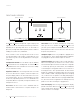
Digital inputs (N
º
5805):
The N
0
5805 has four digital audio input
connectors: an asynchronous USB-B (labeled with a USB icon
), two optical (TOSLINK) S/PDIF connections (labeled T1
and T2) and one coaxial (RCA) S/PDIF connections (labeled C1).
Digital inputs (N
0
5802):
The N
0
5802 has six digital audio input
connectors: An AES/EBU-format XLR connection (labeled
AES/EBU), an asynchronous USB-B digital audio connector
(labeled with a USB icon
),
two optical (TOSLINK) S/PDIF
connectors (labeled T1 and T2), and two coaxial (RCA) S/PDIF
connectors (labeled C1 and C2).
USB port:
This USB Type-A connector allows you to perform
firmware upgrades that may be offered in the future, and to
import and export setup configurations via a standard USB drive
or memory stick (FAT32 formatted). Firmware updates may also
be accomplished via download when the unit is connected to a
local area network (LAN) via an Ethernet cable. (See page 24 for
more detailed firmware update instructions.)
Bluetooth:
Bluetooth-enabled smart devices may be paired
with the N
0
5805 / N
0
5802 to stream audio content wirelessly.
Integrated Qualcomm
®
aptX
™
-HD audio ensures your
Bluetooth
®
wireless enabled device can deliver High Definition
(HD) audio. (See Setup on page 19 for Bluetooth pairing
instructions.)
Line output connectors:
These RCA jacks provide a line-level
left-channel and right-channel signal that can be used to send
the selected input to an amplifier connected to speakers in a
second listening zone, or a recording device.
Note: The Line outputs are variable and will follow the
settings of the Volume, Balance and Mute controls.
Ethernet port:
This RJ45 jack supports connection to a home
network via Cat5e or CAT6 Ethernet cable and allows you to
access the
Setup
menu and other controls via a browser-based
setup panel.
IR input connector:
This connector accepts IR (infrared) control
signals from other equipment. See www.marklevinson.com for
IR code data.
RS-232 port:
This DB9F connector provides serial control
through a standard RS-232 protocol. See www.marklevinson.com
for RS232 code data.
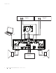
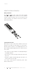
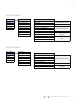
Trigger output connector:
This 3.5mm tip/sleeve connector can
be used to activate other components in the audio system and
listening room, such as amplifiers, lights and window shades. A
12V 100mA DC signal is output whenever the N
0
5805 / N
0
5802 is
on. (See illustration below.)
Trigger input connector:
This 3.5mm tip/sleeve connector
can be connected to the trigger output of another system
component or control system that supplies a trigger voltage.
Whenever the units detects a voltage between 5V and 12V DC at
this connection it will turn ON. When the trigger signal at this
connection ceases the N
0
5805 / N
0
5802 will enter the
Standby
mode. (See illustration above.)
AC Mains connector:
This connector provides AC power to the
N
0
5805 / N
0
5802 when the supplied power cord is connected
from it to an AC electrical outlet. This should be the LAST
connection you make in the hookup process.
We recommend that you unplug the unit from the AC wall outlet
during lightning storms and extended periods of non-use.
NOTE: After connecting all source components to the
N
0
5805 / N
0
5802, we suggest using the
Setup
menu to
set the names of all unused inputs to “Disable.” This
will remove the unused inputs from the list of available
inputs and skip over them when scrolling through inputs.
(See Setup/Input on page 18 for more information.)
CONNECTIONS