
Owner's Manual Media Console N40


3-9
Nº40 Media Console Rear Panel Operation
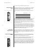
Figure 3-12: RS-232 ports pin connections.
Nº40 Communications
Port
The two “halves” of the Nº40 (the video processor and the audio
processor) need to be able to “talk to each other” in order to coordi-
nate their efforts. The Nº40 communications port on each
component is reserved for this purpose.
Please connect this connector and similarly-labelled connector on
the other component, using the supplied RJ-11 communications
cable. After having done so, power up both units and please wait
until their standby LEDs begin blinking together, indicating that
the initialization and self-test routines are complete and the system
has entered standby.
DC Triggers
Each of the three remote on/off triggers can be configured by your
installer to provide either 5V or 12V DC trigger signals.
These programmable triggers can be used to control other manufac-
turers’ power amplifiers, or to lower a projection television screen,
close drapes, or almost anything else you (or your installer) might
imagine. The most common way of controlling them is as part of a
sound profile, although your installer can also control them via RS-
232 commands, or via IR commands. Please see The Nº40 Menu
System for more detail on using sound profiles.
The tip polarity and power rating for each of these triggers is as
shown below:
Figure 3-13: DC trigger tip polarity.
IR input
A 1⁄8" mini-jack labeled IR input near the lower right corner of the
rear panel provides direct access to the infrared control circuitry of
the Nº40’s main zone.
The incoming signal for the remote IR input should conform to
widely-accepted IR repeater standards: that is, the signal present
should be between 5-12 volts DC, with a positive tip polarity, as
shown below:
5V @ 120 mA
12V @ 60 mA
can sink 120 mA at 0V