8000 & 8200 SERIES FULL SIZE ELECTRIC CONVECTION OVENS INSTALLATION - OPERATION - MAINTENANCE MODELS 8000 - single standard depth oven 8092 - double standard depth oven 8200 - single bakery depth oven 8292 - double bakery depth oven 44 Lakeside Avenue, Burlington, Vermont 05401 USA Telephone: (802) 658-6600 Fax: (802) 864-0183 www.mfii.com PN 14-0396 Rev A (9/14) © 2014 - Market Forge Industries Inc.
Your Service Agency’s Address: Model Serial number Oven installed by Installation checked by
TABLE OF CONTENTS IMPORTANT WARNING: Improper installation, adjustment, alternation, service or maintenance can cause property damage, injury or death. Read the installation, operation and maintenance instructions thoroughly before installing or servicing this equipment. FOR YOUR SAFETY Do not store or use gasoline or other flammable vapors or liquids in the vicinity of this or any other appliance.
Introduction IMPORTANT INFORMATION SERVICE All Market Forge Industries, Inc. equipment is manufactured for use with the type of electrical rating specified on the rating plate and for installation in accordance with National Electrical Code ANSI /NFPA-70 (latest edition) and/or Canadian National Electrical Code CSA-C22.1 as applicable.
Oven Location & Electrical Connection AIR SUPPLY AND VENTILATION ELECTRICAL CONNECTION The area, around and above the appliance must be kept clear to avoid and obstruction of air flow needed for ventilation. Adequate clearance must be maintained at all times in front and side of the appliance for servicing and proper operation. WARNING Disconnect power supply before cleaning or servicing. Convection ovens have a single point power connection at the terminal block.
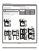
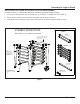
Service Connections 8000 & 8092 STANDARD DEPTH OVENS SERVICE CONNECTIONS EP ELECTRICAL SPECIFICATIONS Power Supply - 1-3/8” (44mm) Ø access holes for power supply wires. Use wire suitable for at least 90°C. Normal amps per line wire per oven: 9kW AMPS VOLTS Installation Clearance: When installing ovens against combustible or non-combustable surfaces (rear or side walls) 0” clearance is required.
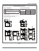
Service Connections 8200 & 8292 BAKERY DEPTH OVENS SERVICE CONNECTIONS ELECTRICAL SPECIFICATIONS EC Electrical Connection - Connection for incoming power supply wire on terminal block. EP AMPS VOLTS Power Supply - 1-3/8” (44mm) Ø access holes for power supply wires. Use wire suitable for at least 90°C. Normal amps per line wire per oven: 12kW Installation Clearance: When installing ovens against combustible or non-combustable surfaces (rear or side walls) 0” clearance is required.
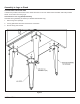
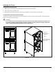
Assembly to Legs or Stand CASTER INSTALLATION ON LEGS If casters are provided, match holes on the caster with holes on the oven bottom base and fasten with bolts provided. NOTE: Front casters are locking type. Instructions for oven Leg (Stand) Assembly: Assemble the leg assembly as follows: (For 8000 & 8200 Models Only) 1. Remove legs from package. 2. Line leg plate holes with holes at the bottom of the base. 3. Secure with (4) 3/8-16 bolts.
Assembly to Legs or Stand INSTRUCTIONS FOR OPTIONAL BOTTOM SHELF AND RACK GUIDE ASSEMBLY: Assemble as follows: (For 8000 & 8200 Models with Standard Leg Assembly already Installed) 1. Line up bottom shelf hole with holes on the legs and secure with #10 x 1/2 SMS as shown on detail “B” 2. Fold up the inner tab about 90○ on each leg using pliers. Fold as shown on detail “A” 3.
Stacking the Ovens ASSEMBLING STACKED OVEN: 1. Match holes on the legs with oven bottom base and screw with bolts provided. 2. Set top oven on top of bottom oven. 3. Bolt down at rear and front as shown. Remove top kick plate to access screwing the front bolts. CASTER INSTALLATION ON STACKED OVENS: If casters are provided, match holes on the caster with holes on the oven bottom base and fasten with bolts provided. NOTE: Front casters are locking type.
Start Up FLEXIBLE COUPLING, CONNECTORS AND CASTERS FINAL PREPARATION On initial installation, turn the oven to 250 degrees and operate for about 1 hour, then reset the thermostat to its maximum and operate for another hour. This will drive off solvents remaining in the unit. At the end of this second hour, turn the thermostat OFF, open the door and set the switch to ‘cool’. Oven should then be thoroughly washed using hot, soapy water before being used.
Control Panel OPERATING INSTRUCTIONS 7. Close doors. Set timer for desired cooking time. 1. Check that power is available to the oven. 8. Buzzer will sound at end of preset interval. Oven is ready to unload. 2. Arrange shelf positions according to the item to be cooked. If oven temperature is to be lowered, set the thermostat to the desired temperature to cool interior. Press the cool down switch. The fan will continue to run with no heat. 3. Close doors. Move fan switch to HIGH or LOW.
Cleaning PERIODIC CLEANING Any piece of equipment works better and lasts longer when maintained properly. Cooking equipment is no exception. Your MARKET FORGE INDUSTRIES, INC. oven must be kept clean during the working day and thoroughly cleaned at the end of the day. Check the ventilation system periodically to see that nothing has fallen down into the exhaust vents. Lubricate the pivot pins of the oven door hinge. Use a multi-purpose lubricating oil sparingly so as to not drip oil needlessly.