OWNER’S MANUAL STEAM-TECHTM ELECTRIC STEAM COOKER MODELS: ST-3E ST-6E INSTALLATION, OPERATION, MAINTENANCE, SERVICE AND PARTS MANUAL An Employee Owned Company 35 Garvey Street • Everett • MA 02149 Tel: (617) 387-4100 • Fax: (617) 387-4456 • Toll Free: (866) 698-3188 • Outside MA Fax: (800) 227-2659 E-mail: custserv@mfii.com • Web site: www.mfii.com FORM NO. S-2470 REV. A 08/06 Printed in U. S. A.
TABLE OF CONTENTS INTRODUCTION DESCRIPTION .......................................................... 1 BASIC FUNCTIONING . ............................................ 1 SERVICE . ................................................................. 1 INSTALLATION ASSEMBLY ............................................................... 2 SETTING IN PLACE ................................................. 2 SERVICE CONNECTIONS ....................................... 2 WATER CONNECTIONS ......................
INTRODUCTION DESCRIPTION: The Steam-Tech represents the latest in counter top steam technology, designed to apply the benefits of steam cooking to today’s health-conscious menus. Ideal for batch cooking, à-la-carte and rethermalization of individual entrées, the Steam- Tech puts the power of steam on your countertop.
INSTALLATION ASSEMBLY: The assembled Steam-Tech™ Pressureless Steam Cooker is shipped in a carton on a skid. Steps required for assembly are as follows: 1. Remove the carton and the unit off the skid. 2. Install the feet into the threaded mounting locations on the bottom of the unit. 3. Mount the left and right pan support racks on the mounting brackets located inside each of the cooking compartments. 4. Mount the drip trough to the front of the unit.
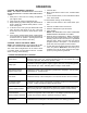
INSTALLATION 20.4" 518mm 15.8" 400mm 13. 3" 76mm E - Electrical Connection CW - Cold Water 2" D - Drain Connection 51mm D CW E 1" 25mm 24" 610mm 5 Pan 23.2" 589mm 3 Pan 16.7" 424mm 14. 15. 16. 17. 4" 102mm 3" 76mm 2" 51mm 18. 1.5" 38mm 19. 30" 762mm D .5" 13mm 20. Fig. 1 Dimensions 8. Remove the four screws in the right side hinge mounting holes and install them in the left side hinge mounting holes (where the hinges were originally mounted). 9.
INTRODUCTION 21. Square the door to the unit by raising or lowering the hinge side of the door, keeping the latch centered with the striker. 22. 22. Visually inspect the door. Be sure that the door is square to the unit, the striker is centered with the latch, and the gasket is in contact with the entire lip of the cooking compartment. 23. 23. Gently open the cooking compartment door, tak- ing care not to move it out of position. 24. Tighten all 4 door hinge bracket mounting screws. 25.
INSTALLATION Fig.
INSTALLATION Fig.
INITIAL SYSTEMS INSPECTIONS GENERAL: This section contains information for you to test and familiarize yourself with the operation of the Steam-Tech. After the cooker is completely assembled, all packaging materials removed, and all service connections are made, all systems must be given a thorough check-out before being put into operation. Be sure that the cooking compartment is empty, and both pan support racks are in place. Confirm that all service connections are correct.
OPERATION COOKING - MECHANICAL CONTROLS: NOTE: THE GREEN STEAMER READY LIGHT MUST BE ON BEFORE ANY CONTROLS BECOME OPERATIONAL. 1. Slide pans of food into the cooking compartment pan support racks. 2. Firmly close the cooking compartment door. 3. Begin steaming by either rotating the selection/timer knob to either the constant steam position or a desired cooking time. 4.
OPERATION DAILY CLEANING: After each period of daily operation (more frequently as required to maintain cleanliness) the cooker should be thoroughly cleaned by completing the following steps: tor needs to be cleaned. Your steamer permits you to quickly clean the generator. The cleaning sequence is as follows: • The red “CLEAN” light illuminates when scale buildsup in the tank and on the heating element 1.
OPERATION Fig.
OPERATION Fig.
OPERATION Fig.
PRINCIPLES OF OPERATION GENERAL: The Steam-Tech represents the latest in counter top steam technology, designed to apply the benefits of steam cooking to today’s health-conscious menus. A “closecoupled” steam generator system gives quick start-ups and efficient steam transfer to the cooking compartment, without the use of fans or expensive blower motors.
TROUBLE-SHOOTING GENERAL: The information in this section is intended to assist the operator, maintenance and the service personnel in locating the source of problems which may occur with the cooker. Before following any of the procedures given in this section, the operator/maintenance person should be thoroughly familiar with the operation section of this manual. WARNING: When you turn the power on, there are terminals that carry 120 volts.
TROUBLE-SHOOTING Fig.
TROUBLE-SHOOTING TROUBLE PROBABLE CAUSE REMEDY POWER light does not come on when 1. the POWER switch is pressed into the 2. ON position 3. No 120v power to unit. 1. Be sure 120v power supply is on. Fuse blown. 2. Replace fuse. Faulty POWER switch. 3. Check/replace POWER switch (P/n 08-6549). Water enters the steam generator very 1. slowly. Dirty strainer screen in the water fill 1. solenoid valve. 2. Dirt or lime accumulation on seat of 3. water fill solenoid valve. 2.
TROUBLE-SHOOTING TROUBLE PROBABLE CAUSE Generator doesn’t drain when the POW- 1. ER switch is pressed into the OFF position. 2. 3. CLEAN GENERATOR light stays on 1. after it has been cleaned (delimed) and rinsed. 2. Unit fails to hold. REMEDY Clogged or kinked generator drain 1. line. Clogged generator drain hole. Check to be sure that the generator drain line is not kinked and is free of debris. Faulty generator solenoid drain 2. valve. 3.
MAINTENANCE tomatic indicator light which tells you when the steam generator needs to be cleaned. front of the unit. CAUTION: Be sure to disconnect the power supply from the unit before servicing any electrical components. CLEANING INSTRUCTIONS: The cleaning sequence is as follows: • The red “CLEAN” light illuminates when scale buildsup in the tank and on the heating element Procedure: 1. Remove the 6 screws that fasten the control panel assembly onto the front of the unit. 2.
MAINTENANCE square to the unit, the striker is centered with the latch, and the gasket is in contact with the entire lip of the cooking compartment. gasket leak, readjust the door gasket to the unit or replace it. Procedure: Replace Gasket: 1. Open the cooking compartment door. 2. Remove the (3) screws from the top of the door, and the (3) screws from the bottom of the door. 3. Remove the inner door, gasket plate and gasket. 4. Remove the (6) nuts on the back of the inner door. 5.
ILLUSTRATED PARTS LIST FIGURE 7.1 TOP LEVEL ASSEMBLY Fig.
ITEM ST-3E PART NO. ST-6E PART NO. 1 REF. --- BOILER ASSY. 1 2 REF. --- ELECTRICAL ASSY. 1 3 08-6498 --- SOLENOID VALVE 1 4 10-1055 --- ELBOW, STREET, 3/8” NPT 2 5 08-4863 --- HOSE BARB, 3/8” NPT X 1/4 ID HOSE 2 6 91-7652 91-7653 PANEL, SIDE 2 7 REF --- PLUMBING ASSY. 1 8 91-6838 91-6839 GASKET, INLET 1 9 91-7690 --- BRACKER, REED SWITCH 1 10 08-6308 --- REED SWITCH 1 DESCRIPTION QTY.
ILLUSTRATED PARTS LIST LIST OF HEATING ELEMENTS PART NO. MODEL NO. kW RATING VOLTAGE 08-6485 ST-3E 9 208 08-6486 ST-3E 9 240 08-6487 ST-3E 9 480 08-6491 ST-6E 14 208 08-6492 ST-6E 14 240 08-6493 ST-6E 14 480 ITEM NO. PART NO. 1 91-7707 BOILER BODY WELD ASSY.
ILLUSTRATED PARTS LIST Fig. 12 Door Assembly ITEM NO. ST-3E PART NO. ST-6E PART NO. DESCRIPTION QTY.
ILLUSTRATED PARTS LIST Fig. 13 Electrical Subassembly ITEM NO. PART NO. 1 91-7718 ELECTRIC PLATE 1 08-6328 LIQUID LEVEL BOARD 1 2 3 DESCRIPTION QTY. SEE NOTE 2 CONTACTOR 1 4 08-6479 FUSE BLOCK 2 5 08-6468 FUSE 5A 2 8 08-6472 RELAY 2 7 08-6475 RELAY BASE 2 8 09-6575 BUSHING, PLASTIC 9 08-6450 120 TO 240V TRANSFORMER SEE NOTE 1 10 08-6472 RELAY SEE NOTE 1 11 08-6475 RELAY BASE SEE NOTE 1 1 NOTES: 1. One of each of these components are used on digital only.
ILLUSTRATED PARTS LIST Fig. 14 Mechanical Panel with Cook & Hold Assembly ITEM NO. ST-3E PART NO. ST-6E PART NO. Fig. 15 Digital Panel Assembly DESCRIPTION QTY.
ILLUSTRATED PARTS LIST Fig. 16 Plumbing Assembly ITEM NO. PART NO. 1 SEE NOTE 2 DESCRIPTION QTY. ELBOW, STREET, HOSE BEAD 1 08-5021 DRAIN VALVE 1 3 10-3862 REDUCER 1 4 10-1014 NIPPLE, CLOSED 2 5 10-1055 STREET ELBOW 3 8 10-1054 TEE 1 7 08-6498 SOLENOID 1 8 08-4863 HOSE BARB 1 9 10-3684 COMPRESSION FITTING 1 NOTE: 3 pan units use part number 08-5072 and 6 pan units use part number 10-0937.