ST-6-TGG™ and ST-12-TGG™ PRESSURELESS STEAM COOKER WITH GAS GENERATORS WARNING Improper Installation, adjustment, alteration, service, or maintenance can cause property damage, injury, or death. Read the installation, operating, and maintenance instructions thoroughly before installing or servicing this equipment. FOR YOUR SAFETY Do not store or use gasoline or other flammable vapors or liquids in the vicinity of this or any other appliance.
TABLE OF CONTENTS PARAGRAPH PAGE PARAGRAPH SECTION 1 INTRODUCTION 1.1 1.2 1.3 Description ............................................ 1-1 Basic Functioning ................................. 1-1 Service ................................................. 1-1 4.1 4.2 4.3 4.3.1 4.3.2 4.3.3 4.3.4 4.3.5 4.3.6 SECTION 2 INSTALLATION 2.1 2.2 2.3 2.4 2.5 2.6 2.6.1 2.6.2 2.6.3 2.6.4 2.7 Assembly ............................................. 2-1 Setting in Place ....................................
LIST OF ILLUSTRATIONS FIGURE PAGE SECTION 3 OPERATION 3-1 SECTION 6 ILLUSTRATED PARTS LIST Controls and Indicators ......................... 3-2 See Page 6-1 SECTION 4 TROUBLESHOOTING 4-1 4-2 Wiring Diagram, Model ST-6 ................. 4-5 Schematic Diagram, Model ST-6 ....................................... 4-9 LIST OF TABLES TABLE PAGE TABLE SECTION 3 OPERATION 3-1 SECTION 4 TROUBLESHOOTING Controls and Indicators ......................... 3-2 4-1 4-2 iv Form No. S-4846 Rev.
1. INTRODUCTION This service and parts manual contains general information, installation operation, principles of operation, troubleshooting, and maintenance information for the Market Forge ST-6 Pressureless Steam Cookers. Also included is a parts list in which each replaceable part is identified and shown in an accompanying exploded view. 1.
2. INSTALLATION 2.1 ASSEMBLY The boiler and its individual shut-off valve must be disconnected from the gas supply piping system during any pressure testing of that system at test pressure in excess of 1/2 psig (3.45 k/PA). The wiring diagram adhesive label is located on the inside of the front panel. This product must be installed in a room with adequate air supply.
2. INSTALLATION (cont’d.) CAUTION d. Natural gas units are equipped with a pressure regulator factory-adjusted to give 4" (102 mm) water column manifold pressure. e. Propane gas units are equipped with a pressure regulator factory-adjusted to give 10" (254 mm) water column manifold pressure. f. Refer to “Gas Burner Adjustment Instructions” (page ___). g. ONLY A LICENSED GAS FITTER SHOULD MAKE GAS LINE CONNECTIONS. Do not connect hot water to the cold water condenser water inlet. 2.
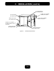
2. 2.6.4 INSTALLATION (cont’d.) Shut-Down Procedure 11. Remove the door latch assembly form the face of the unit. The two (2) nuts mounting the door latch are located behind the face of the unit and must be accessed where the rightside panel was removed. 12. Remove the two (2) white hole plugs from the left door latch mounting holes, and insert them into the right door latch mounting holes (where the door latch assembly was originally mounted ). 13.
2. INSTALLATION (cont’d.) TOP RIGHT HINGE MOUNTING HOLES INTERLOCK ASSEMBLY ORIGINAL POSITION TOP LEFT HINGE MOUNTING HOLES DOOR LATCH ASSEMBLY ORIGINAL POSITION LEFT DOOR LATCH MOUNTING HOLES INTERLOCK ASSEMBLY POSITION WHEN DOOR IS REVERSED LOWER LEFT HINGE MOUNTING HOLES LOWER RIGHT HINGE MOUNTING HOLES Figure 2-1. TYPICAL DOOR LAYOUT MARKET FORGE INDUSTRIES, INC. 35 GARVEY STREET EVERETT, MA 02149 TEL: 617-387-4100 TELEX: 91-9494 FAX: 617-387-4456 OUTSIDE MA: 800-227-2659 Form No.
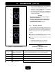
3. OPERATION 3.1 OPERATING CONTROLS AND INDICATORS 4. Set appropriate timer to the required cooking time (see Test Kitchen Bulletin in Section 3.5). 5. Turn off buzzer, which sounds to indicate cooking is complete, by setting timer dial (1) to the OFF position. 6. Open door sightly at first letting most of the steam out of the compartment and then fully open the door. 7. Unload by sliding pans of food from pan supports, taking care to avoid hitting compartment opening.
3. OPERATION (cont’d.) 1. Press the power switch into the “OFF” position. The steam generator will automatically drain. 2. Clean the cooking compartment as described in Section 3.3.1 of this manual. 3. The steam generator must be rinsed and drained. Refer to Section 3.4, Cleaning the Generator, for complete instructions. CAUTION • Disconnect the power supply to the steam generator before servicing.
3. OPERATION (cont’d.) 3. Turn power switch off and drain the steam generator that needs cleaning. 4. Turn the power switch on. 5. Remove the cleaning solution inlet cap located on the right hand side of the upper brow. 6. Using a kitchen funnel, pour Market Forge’s TOTAL CONCEPT™ deliming solution (P/n 20-0318) into the generator (2 quarts). 7. Add 5 quarts of water to fill the generator to 3/4. The heater relay will click on.
3. OPERATION (cont’d.) 3.5 TEST KITCHEN BULLETIN Model ST-6- & 12-TGG Pressureless Cooker Facts On Parade 1. Frozen vegetables should always be cooked in perforated 12” x 20” x 21/2” (1/1 65mm) pans 71/2 lbs (34 kg) maximum per pan. 2. Frozen entrees should be underlined with a perforated pan for best results. If they are defrosted first, the heating time will be decreased. 3. Fresh foods may also be cooked in this unit.
3. OPERATION (cont’d.) The ST-6-TGG pressureless cooker is a two-compartment unit. Each compartment holds three 12” x 20” x 21/2” or 12” x 20” x 4” pans. This unit enables the cook to prepare foods close to the time of service. The cooking times given are timer settings and should be set on a preheated compartment. There is a thermostatic time delay in each compartment that adjusts the total time depending on the temperature and amount of the food.
3. OPERATION (cont’d.) PRESSURELESS STEAM COOKING TIMER SETTINGS AND PORTIONS VEGETABLES ITEM Beans, Snap Green or Waxed Beets (50 mm) 2” Diameter Broccoli 1/2-3/4” (12-20 mm) Stalks Carrots Sliced Cauliflower, Trimmed 1 1/2-2” (38-50 mm) Corn on Cob Husked Cabbage 1/4-1/6 of Head, Cored Onions, 2” (50 mm) Diameter Peas, Shelled Potatoes, French Fry Cut Potatoes, Regular Cut, 3” (75 mm) Spinach, Cleaned Cut Squash, Summer, Sliced 1” thick (25 mm) Squash, Winter Peeled Turnip, Diced Approx.
3. OPERATION (cont’d.) PRESSURELESS STEAM COOKING TIMER SETTINGS AND PORTIONS (continued) MEAT—POULTRY—FISH ITEM Approx. Frozen Recommended 12” x 20” (1/1) Weight Perforated Pan Per Pan Number of Pans Timer Settings in Minutes Approx. Number Cooked Servings Per Pan 8 lbs (3.6 kg) 2 1/2” (65mm) 1-3 20-30 3 each 4” (100 mm) 1-3 45-50 2 each 4” (100 mm) 1-3 50-60 15-20 2 oz. Protein (55 g) 25-30 2 oz. Protein (55 g) 20-25 2 oz. Protein (55 g) Fish, Fillets 3 lbs (1.
4. TROUBLESHOOTING 4.1 GENERAL 4.3 ELECTRICAL TROUBLESHOOTING PROCEDURES The information in this section is intended to assist both the operator and service personnel in locating the general source of problems that may occur with the cooker. Before following any of the procedures given in this section, the operator should be thoroughly familiar with the operating instructions and the function of all controls that are described in Section 3.
4. TROUBLESHOOTING (cont’d.) TABLE 4-1 (cont’d.) PROBLEM PROBABLE CAUSE REMEDY 5. GENERATOR WILL NOT CREATE STEAM. a. 120V power supply is not connected or turned on. b. Cooking compartment door is ajar. c. Cooking compartment door is out of alignment. d. Faulty door magnet or magnetic reed switch. e. Lime build-up on probe. f. Faulty steam relay or contactor. g. Faulty control panel TIMER. h. Faulty MODE selector switch. i. Wiring short. a. Check to be sure 120V power is connected and on. b.
4. TROUBLESHOOTING (cont’d.) TABLE 4-1 (cont’d.) PROBLEM PROBABLE CAUSE 10. STEAM ENTERS COMPARTMENT CONTINUOUSLY. TIMER DIAL NOT TURNING. 11. STEAM CONTINUES TO FLOW INTO COMPARTMENT AND/OR BUZZER FAILS TO SOUND AT END REMEDY a. Constant steam position. b. Faulty thermostatic switch. c. Faulty timer motor. d. Faulty wiring. a. Move knob to timing location. b. Replace switch. See Subsection 5.4.8. a. Timer contacts faulty. b. Buzzer faulty. c. Faulty wiring. a. Replace timer. See Subsection 5.4.4.
4. TROUBLESHOOTING (cont’d.) TABLE 4-2 ELECTRICAL FAULT ISOLATION GUIDE FAILURE FAULT LOCATION 1. Will not operate in either CONSTANT STEAM or 60-MINUTE TIMER positions. a. Incoming power b. Timer c. Door interlock switch d. Wiring 2. Operating in CONSTANT STEAM position but not in 60-MINUTE TIMER position. a. 60-minute timer b. Wiring 3. Operates in 60-MINUTE TIMER position but not in CONSTANT STEAM position. a. Timer b. Wiring 4. Steam solenoid valve fails to open with indicator light on. a.
Figure 4-1.
4. TROUBLESHOOTING (cont’d.) move the control panel (see Subsection 6.3.4), and proceed as follows: does not enter the compartment and the indicator light fails to turn on with the door latch securely engaged, the fault may be in the door interlock switch. Proceed as follows: 1. Turn off power to the cooker at external circuit breaker. 2. Disconnect all five wires from timer terminals (see Figure 5-1). 3. Connect an ohmmeter between terminals 1 and 3. 4.
4. TROUBLESHOOTING (cont’d.) zero ohm reading on the dial. If a zero ohm reading is not obtained, the switch is defective. 4. Shut off cooker, disconnect ohmmeter leads, and replace wires on switch terminals. 4.3.7 as shown. Connections can be easily removed. Figure 5-2 shows the same information schematically and is an aid in isolating circuits for testing. Using an ohmmeter, wiring continuity between the connections shown on the wiring diagram (Figure 5-1) is readily verified.
4. TROUBLESHOOTING (cont’d.) WARNING: When you turn the power on, there are terminals that carry 120 volts. Protect the ends of these disconnected wires to prevent shorting to hot leads. 3. Disconnect the jumper. 4.4.2 4. Turn power ON. Using the voltmeter, check that the power being supplied to terminals L1 and L2 is 120 volts, plus 10%, minus 15%. 4.4.1 1. With the power ON, the LED next to the Low Water Relay should be OFF. Using the voltmeter, touching the probes to the L2 and N.O.
4. TROUBLESHOOTING (cont’d.) ST-6 TGG (2) COMPARTMENT TOP BOTTOM Figure 4-2. Schematic Diagram, Model ST-6 TGG MARKET FORGE INDUSTRIES, INC. 35 GARVEY STREET EVERETT, MA 02149 TEL: 617-387-4100 TELEX: 91-9494 FAX: 617-387-4456 OUTSIDE MA: 800-227-2659 Form No. S-48466 -Rev.
5. MAINTENANCE 5.1 GENERAL 5.3 REPAIR AND REPLACEMENT This section contains both preventive and corrective maintenance information. Preventive maintenance may be performed by maintenance personnel at the establishment in which the cooker is installed. It is recommended that user personnel never attempt to make repairs or replacements to the equipment without the assistance of authorized service.
5. 5.3.3 MAINTENANCE (cont’d.) Door Gasket Replacement 5.3.4 WARNING The cooking compartment door gaskets are made of a silicone-type rubber material that is very durable but subject to wear during normal operation. Should the gasket leak, readjust the door gasket to the unit or replace it.
6. ILLUSTRATED PARTS LIST 6.1 GENERAL 6.3 INDEX OF ILLUSTRATED PARTS LIST This section contains a complete listing of all replaceable parts of the ST-6 TGG and ST-10 TGG. For the purpose of parts identification, the unit is broken down into functional assemblies, and each assembly is shown in an exploded view that is keyed to the accompanying parts list. Each parts list contains the figure index number, the Market Forge part number, and an abbreviated description.
6.
ITEM NO. PART NO.
6.
6. ILLUSTRATED PARTS LIST ITEM NO. PART NO. ST-6TGG PART NO.
6. ILLUSTRATED PARTS LIST ITEM NO. PART NO.
6. ILLUSTRATED PARTS LIST ITEM NO. PART NO. 1 2 3 4 5 6 97-5988 97-5987 97-5988 97-5987 97-5989 97-5988 Drain Box DESCRIPTION DRAIN BOX ASSY PLUG, 1/4-18 NPT ELBOW, 3/4 C x 3/4 MPT BLOW DOWN VALVE CONNECTOR, 3/4 C x 3/4 MPT UNION ELBOW, 3/4" ITEM NO. PART NO. 1 2 3 4 5 6 7 8 9 10 11 97-5990 97-5975 97-5949 97-5974 97-5992 97-5864 97-5986 97-5948 97-5960 97-5991 97-5945 Component.
6. ILLUSTRATED PARTS LIST ITEM NO. PART NO. 1 2 3 4 5 6 7 8 9 10 11 97-5954 97-5923 97-5971 97-5994 97-5927 97-5953 97-5929 97-5969 97-5856 97-5933 97-5933 97-5958 ITEM NO. PART NO.
6. ILLUSTRATED PARTS LIST ITEM NO. PART NO. ST-6TGG PART NO. ST-12TGG 1 91-5729 91-7692 OUTER DOOR 1 2 91-5766 91-7694 INNER DOOR 1 3 91-5731 91-7696 GASKET RETAINING PLATE 1 4 91-5286 91-7783 DOOR GASKET 1 5 91-5745 91-5745 DOOR HANDLE 1 6 09-1608 09-1608 STRIKER 1 7 08-5027 08-5027 MAGNET 1 8 91-5901 91-5901 MAGNET BRACKET 1 9 08-4600 08-4600 COMPRESSION SPRING 2 DESCRIPTION 6-9 QTY.
6.
6. ILLUSTRATED PARTS LIST ITEM NO. PART NO. 1 98-3809 FRAME & DRAIN ASSEMBLY 1 2 98-3826 GAS CONTROL BOX ASSEMBLY- ELECTRICAL 1 3 98-0090 BURNER TUBE 4 4 98-3846 BURNER, IGNITOR, & SENSOR ASSEMBLY 2 5 98-0124 GENERATOR, BOILER ASSY 2 6 08-4942 ELBOW, 90, 1" N.P.T. STEEL 1 7 08-4988 ELBOW, 45, 1" N.P.T. STEEL 1 8 08-1207 BARB, HOSE 1" N.P.T. X 1" HOSE 2 DESCRIPTION QTY. 9 98-3817 PLATE, FRONT BURNER COVER, 2 10 10-8105 THERMOSTAT, DRAIN BOX, 3/8" N.P.
6. ITEM NO. ILLUSTRATED PARTS LIST PART NO. PART NO. ST-6TGG ST-12TGG DESCRIPTION QTY. 1 98-3504 91-6489 CONTROL PANEL 1 2 98-3507 91-7612 ARTWORK, CONTROL PANEL 1 3 08-6464 08-6464 60 MIN.
6. ILLUSTRATED PARTS LIST ITEM PART NO. 1 98-3822 2 10-6005 3 08-6472 4 08-6475 5 08-7130 6 08-6328 7 08-6450 8 08-3515 9 10-2509 10 10-2425 11 10-2339 98-3841 98-3840 GAS CONTROLS ASSY DESCRIPTION WELDMENT ASSY. BOX, GAS CONTROL TERMINAL STRIP, (TB-2A & TB-2B) RELAY, 120 VAC (RI-A & R1-B) RELAY SOCKET, 120 VAC (RI-A & RI-B) IGNITION MODULE (IM-A & IM-B) LIQUID LEVEL BOARD (LLB-A & LLB-B) TRANSFORMER 120/24 VAC. (XF-A & XF-B) SCREW, #6 X 3/4"LG. "F" THREAD CUTTING WASHER, LOCK #10, (GRD.
6. ILLUSTRATED PARTS LIST ITEM 1 2 3 4 5 6 7 8 9 PART NO. 10-3452 10-3494 10-3332 08-4960 08-7568 10-3324 08-5070 08-7848 10-2660 GASLING ASSY DESCRIPTION TEE, M.I. 1/2" X 1/2" X 1/2" N.P.T. NIPPLE, M.I. 1/2" N.P.T. X 2.25" LG UNION, M.I. 1/2" N.P.T X 1/2" N.P.T. NIPPLE, CLOSE 1/2" N.P.T. VALVE, GAS #SC-300 1/2" X 1/2" N.P.T. BUSHING, REDUCER-M.I. 1/2" X 1/4" N.P.T ELBOW, 90 BRASS - 1/4" FLARE X 1/4" N.P.