
Fan User Manual


NEW HOME INSTALLATION
MODELS 761, 763, 765, 768IC, AND 770IC
NOTE: Plastic scroll and motor assembly can be removed from
the metal housing prior to step one if desired. Simply loosen four
mounting screws securing scroll to housing and slide it towards
the outlet box. Carefully lift and tilt scroll, motor and wheel assem-
bly to remove it from housing. (See Fig. 1 & 2.)
1. Pull motor plug from receptacle. Remove outlet box cover and
desired knockout from housing.
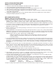
2. If the duct adapter is attached, disregard this note. Attach
duct adapter to housing by first hooking mounting flange
over edge of air discharge opening. Pivot duct adapter
insuring (2) aligning tabs are inside opening and align (2)
locking tabs with small rectangular holes. Press firmly into
holes to lock. See Fig. 3. Remove tape securing damper.
NOTE: The attachment of the duct adapter to the housing may
be reinforced if desired, by installing a #8AB screw through the
oblong hole in the duct adapter and the small round hole in
the housing.
3. Insert mounting brackets with angle pointing away from
housing. Position housing into ceiling location. Housing is
stamped to show a line at 3/8” for drywall and 3/4” for standard
sheetrock and plaster. Fasten securely through mounting
holes provided in housing. (Fig. 4.) Pull mounting brackets
against adjacent ceiling joist and fasten securely. (Fig. 5.)
4. Run 120vAC, 60 Hz power cables from wall switch/switches to
appropriate knockout in housing. Use a BX or Romex con-
nector. (Refer to wiring diagram designated for the model
being installed.) Connect cables from wall switch/switches to
receptacle wires using approved wire connectors. Connect
ground wire to green screw or lead in outlet box. Install outlet
box cover and secure with screw provided.
5. Run four inch round duct from fan air discharge outlet to wall
cap or roof cap. See Figs. 6 & 7.
IMPORTANT: Be sure nothing obstructs the discharge of the fan.
Take precautions to insure that insulation does not get into
duct work or fan discharge opening, and damper opens and
closes freely.
6. Carefully replace plastic scroll, motor and wheel assembly if
unit was disassembled for installation. Reverse procedure as
noted. Tighten screws securely and push plug into motor
receptacle.
7. (MODELS 761, 763 & 765 ONLY)
Squeeze springs on grille and insert in tabs located in housing.
See Fig. 1. Press grille firmly into place.
8. (MODELS 768IC & 770IC ONLY)
Center reflector in center of grille. Push light plug into recepta-
cle. Center reflector/grille assembly over housing and engage
1” mounting bolt through center hole in reflector into metal
mounting bracket located on plastic scroll and motor
assembly. Tighten bolt until grille is firmly pulled against the
ceiling. See Fig. 2.
9. Install light bulb. (Type A-19, 100 watts maximum.)
10. Install the snap-on lens by engaging lens tabs into grille
slots.
FIG. 3
FIG. 4
FIG. 5
LOCKING
TABS
MOUNTING
FLANGE
DUCT ADAPTER
ALIGNING