
Specifications
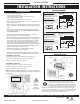
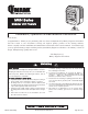

MUH SERIES
470 Beauty Spot Rd. E, Bennettsville, SC 29512
visit www.qmarkmep.com for more info
ARCHITECT’S AND ENGINEER’S SPECIFICATIONS*
•
Unit mounts either horizontally or vertically. Totally versatile. For factories,
warehouses, garages, stores, shipping rooms, power stations, aircraft hangers.
Can be used for primary, supplementary, spot, or dual-system heating.
•
Wide range of optional control kits are field installable, increasing the MUH
adaptability to the specification market.
•
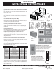
Forced air unit heater with 10 power ratings; from 3KW to 50 KW heating
output; 208, 240, 277 and 480V, 10,230 to 170,500 BTU/hr.
•
32 compatible models (no need to try to assemble a heating system from 70 or
80 models!)
•
Heavy gauge die-formed steel housing. Two-toned, smartly styled.
•
Advanced pull-through air flow design draws air across heating element for
more even air distribution and cooler element operation.
•
Specially designed venturi outlet to meet that added throw as required in
vertical position.
•
Branch circuit fusing (when required).
•
Completely enclosed fan motor.
•
1- or 3-phase wiring on 5 through 10 KW 208/240V and 15 KW 208V units (field
interchangeable).
•
Aluminum-finned, copper clad steel sheath heating element has longer useful
life, because of cooler sheath temperature and faster heat dissipation.
•
24V control transformer standard on most models, providing a safer and more
accurate means of temperature control. 3KW and 5KW, 208-277V, have line
voltage controls as standard (24V control available on made-to-order basis).
•
Automatic reset linear thermal cut-out, capillary type, provides protection over
entire length of element areas (Manual reset protection available on made-to-
order basis).
•
2-speed fan selector switch (25 to 50 KW models).
•
Fan delay feature eliminates cold drafts. Element heats up
before fan cuts in, then fan continues to distribute heat
after element shuts off.
•
Ruggedly built, yet lighter weight for easier installation. No
piping flutes, valves, or traps.
•
Individually adjustable discharge louvers to control air flow.
•
Choice of optional diffusers for variety of air patterns,
maximizing heat concentration and coverage in the vertical
position.
•
Meets all UL, NEC, and OSHA requirements.
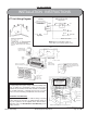
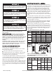
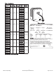
SELECTION CHART
MUH03-81 208 1Ø 3.0 10.2 14.5 208 N/A 350 800 27 ° 208 1600 1/100 8 9 12 AWG 12 27
MUH03-21 208/240 1Ø 2.2/3.0 7.5/10.2 11.0/12.5 208/240 N/A 350 800 27 ° 208/240 1600 1/100 8 9 12 AWG 12 27
MUH03-71 277 1Ø 3.0 10.2 11.0 277 N/A 350 800 27 ° 277 1600 1/100 8 9 12 AWG 14 27
MUH03-31 347 1Ø 3.0 10.2 8.6 347 N/A 350 800 27 ° 347 1600 1/100 8 9 12 AWG 14 27
MUH03-41 480 3Ø 3.0 10.2 3.6 24 N/A 350 800 27 ° 480 1600 1/100 8 9 12 AWG 14 27
MUH03-61 600 3Ø 3.0 10.2 2.9 600 N/A 350 800 27 ° 600 1600 1/100 8 9 12 AWG 14 27
MUH05-81 208 1-3Ø 5.0 17.0 24.0 208 5A 350 800 45 ° 208 1600 1/100 8 9 12 AWG 10 27
MUH05-21 208/240 1-3Ø 3.7/5.0 12.6/17.0 18.0/21.0 208/240 5A 350 800 45 ° 208/240 1600 1/100 8 9 12 AWG 10 27
MUH05-71 277 1Ø 5.0 17.0 18.0 277 N/A 350 800 45 ° 277 1600 1/100 8 9 12 AWG 10 27
MUH05-31 347 1Ø 5.0 17.0 14.4 347 N/A 350 800 45 ° 347 1600 1/100 8 9 12 AWG 10 27
MUH05-41 480 3Ø 5.0 17.0 6.0 24 N/A 350 800 45 ° 480 1600 1/100 8 9 12 AWG 14 27
MUH05-61 600 3Ø 5.0 17.0 4.8 600 N/A 350 800 45 ° 600 1600 1/100 8 9 12 AWG 10 27
MUH-07-8 208 1-3Ø 7.5 25.6 36.0 24 5B 650 970 37 ° 208 1600 1/30 9 14 18 AWG 6 38
MUH-07-2 208/240 1-3Ø 5.6/7.5 19.1/25.6 27.0/31.3 24 5B 650 970 37 ° 208/240 1600 1/30 9 14 18 AWG 8 38
MUH-07-7 277 1Ø 7.5 25.6 27.0 24 5B 650 970 37 ° 277 1600 1/30 9 14 18 AWG 8 38
MUH-07-3 347 1Ø 7.5 25.6 21.6 24 5B 650 970 37 ° 347 1600 1/30 9 14 18 AWG 14 38
MUH-07-4 480 3Ø 7.5 25.6 9.0 24 5B 650 970 37 ° 480 1600 1/30 9 14 18 AWG 14 38
MUH-07-6 600 3Ø 7.5 25.6 7.3 24 5B 650 970 37 ° 600 1600 1/30 9 14 18 AWG 14 38
MUH-10-8 208 1-3Ø 10.0 34.1 48.0 24 5B 650 970 49 ° 208 1600 1/30 9 14 18 AWG 4 38
MUH-10-2 208/240 1-3Ø 7.5/10.0 25.6/34.1 36.0/42.0 24 5B 650 970 49 ° 208/240 1600 1/30 9 14 18 AWG 6 38
MUH-10-7 277 1Ø 10.0 34.1 36.0 24 5B 650 970 49 ° 277 1600 1/30 9 14 18 AWG 6 38
MUH-10-3 347 1Ø 10.0 34.1 28.8 24 5B 650 970 49 ° 347 1600 1/30 9 14 18 AWG 14 38
MUH-10-4 480 3Ø 10.0 34.1 12.0 24 5B 650 970 49 ° 480 1600 1/30 9 14 18 AWG 14 38
MUH-10-6 600 3Ø 10.0 34.1 9.7 24 5B 650 970 49 ° 600 1600 1/30 9 14 18 AWG 14 38
MUH-15-8 208 1-3Ø 15.0 51.2 72.0 24 5A 910 1640 52 ° 208 1530 1/20 11 20 35 AWG 2 53
MUH-15-2 208/240 3Ø 11.2/15.0 38.2/51.2 31.3/36.1 24 5C 910 1640 52 ° 208/240 1530 1/20 11 20 35 AWG 6 53
MUH-15-4 480 3Ø 15.0 51.2 18.0 24 5C 910 1640 52 ° 480 1530 1/20 11 20 35 AWG 10 53
MUH-15-6 600 3Ø 15.0 51.2 14.5 24 5C 910 1640 52 ° 600 1530 1/20 11 20 35 AWG 12 53
MUH-20-8 208 3Ø 20.0 68.2 56.0 24 5A 1320 2060 48 ° 208 1500 1/10 12 23 41 AWG 4 60
MUH-20-2 208/240 3Ø 15.0/20.0 51.2/68.2 41.2/48.0 24 5C 1320 2060 48 ° 208/240 1500 1/10 12 23 41 AWG 4 60
MUH-20-4 480 3Ø 20.0 68.2 24.0 24 5C 1320 2060 48 ° 480 1500 1/10 12 23 41 AWG 10 60
MUH-20-6 600 3Ø 20.0 68.2 19.3 24 5C 1320 2060 48 ° 600 1500 1/10 12 23 41 AWG 12 60
MUH-25-2 208/240 3Ø 18.7/25.0 63.8/85.2 52.0/60.0 24 5A 2100/1800 2100/2030 38 °/44 ° 208/240 1600/1375 1/4 13 23 50 AWG 3 93
MUH-25-4 480 3Ø 25.0 85.2 30.0 24 5C 2100/1800 2100/2030 38 °/44 ° 480 1600/1375 1/4 13 23 50 AWG 8 93
MUH-25-6 600 3Ø 25.0 85.2 24.2 24 5C 2100/1800 2100/2030 38 °/44 ° 600 1600/1375 1/4 13 23 50 AWG 10 93
MUH-30-8 208 3Ø 30.0 102.3 84.0 24 5A 2100/1800 2100/2030 45 °/53 ° 208 1600/1375 1/4 12 20 50 AWG 1 93
MUH-30-2 208/240 3Ø 22.5/30.0 76.7/102.3 63.0/72.3 24 5A 2100/1800 2100/2030 45 °/53 ° 208/240 1600/1375 1/4 12 20 50 AWG 2 93
MUH-30-4 480 3Ø 30.0 102.3 36.0 24 5C 2100/1800 2100/2030 45 °/53 ° 480 1600/1375 1/4 12 20 50 AWG 6 93
MUH-30-6 600 3Ø 30.0 102.3 29.0 24 5C 2100/1800 2100/2030 45 °/53 ° 600 1600/1375 1/4 12 20 50 AWG 8 93
MUH-40-2 208/240 3Ø 30.0/40.0 102.3/136.4 83.4/96.4 24 5A 3000/2600 3260/2900 42 °/49 ° 208/240 1525/1420 1/2 15 28 60 AWG 1/0 114
MUH-40-4 480 3Ø 40.0 136.4 48.0 24 5A 3000/2600 3260/2900 42 °/49 ° 480 1525/1420 1/2 15 28 60 AWG 4 114
MUH-40-6 600 3Ø 40.0 136.4 38.7 24 5A 3000/2600 3260/2900 42 °/49 ° 600 1525/1420 1/2 15 28 60 AWG 6 114
MUH-50-8 208 3Ø 50.0 170.5 139.0 24 5A 3000/2600 3260/2900 53 °/61 ° 208 1525/1420 1/2 15 25 60 AWG 4/0 114
MUH-50-2 208/240 3Ø 37.5/50.0 127.3/170.5 104.2/120.4 24 5A 3000/2600 3260/2900 53 °/61 ° 208/240 1525/1420 1/2 15 25 60 AWG 3/0 114
MUH-50-4 480 3Ø 50.0 170.5 60.2 24 5A 3000/2600 3260/2900 53 °/61 ° 480 1525/1420 1/2 15 25 60 AWG 4 114
MUH-50-6 600 3Ø 50.0 170.5 48.3 24 5A 3000/2600 3260/2900 53 °/61 ° 600 1525/1420 1/2 15 25 60 AWG 3 114
CAT. NO. VOLTS
PHASE KW
ELECTRICAL DATA AIR DELIVERY DATA
BTU/HR.
000
AMPS (3) FPM(2) ∆T(°F) VOLTS RPM(2) HP HORIZ. VERT.
HORI.
AIR
THROW
WIRE
SIZE
INSTALLED
WEIGHT
(LBS.)
W/BRACK.
CFM(2)
CONTROL
VOLT (1)
2 STAGE
ELEMENT
CONTROL
FAN MOTOR DATA
MAXIMUM EFFECTIVE
MOUNTING HEIGHT
Note:
1. All standard units are supplied with a low voltage control transformer and contactor (24V) except
MUH-03 & 05, 208, 240 & 277 volt models. Low voltage control on these units are available on made
to order. All units are also available on special order for 120 volt control; internal and transformer or
external without transformer.
2. On dual voltage units; CFM, FPM, and RPM are shown at higher voltage.
3. On dual phase units, maximum amp draw is listed for respective voltage.
4. 25 thru 50 KW models have two speed motors and dual CFM ratings.
5A. Standard.
5B. Optional - made to order - amp load unbalanced on 3 Phase.
5C. Optional - made to order - amp load balanced on 3 Phase.
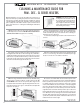
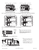
DIMENSIONS
CAT. NO. HEIGHT WIDTH DEPTH
MUH-03 & 05 16” 14” 7
1
/
2
”
MUH-07 & 10 21
3
/
4
” 19” 7
1
/
2
”
MUH-15 & 20 21
3
/
4
” 19” 12
3
/
4
”
MUH-25 & 30 30” 26
5
/
8
”11
3
/
4
”
MUH-40 & 50 30” 26
5
/
8
”17
1
/
8
”
Jefferson Shop Building
Electrical Equipment O&M Manual
Page 135 of 141
Model: MUH-0341
Designation: UH-801, UH-802