OORPHONE DOORPHONE 120 WIRELESS DOORPHONE ™ USER MANUAL 3 GEBRAUCHSANLEITUNG 19 GUIDE UTILISATEUR 35 MODO DE EMPLEO 51 MANUALE D’ISTRUZIONE 67 GEBRUIKSAANWIJZING 83 20194/20080618• DOORPHONE120TM © ALL RIGHTS RESERVED MARMITEK®2007
DOORPHONE 120™ WIRELESS DOORPHONE SAFETY WARNINGS • To prevent short circuits, the handset should only be used only in dry spaces. Do not expose the components to rain or moisture. • Do not expose the components of your systems to extremely high temperatures or bright light sources. • In case of improper usage or if you have altered and repaired the product yourself, all guarantees expire.
INTRODUCTION Congratulations on your purchase of the digital wireless Marmitek DoorPhone120™. Using this door phone, you can speak to the person at the door from any spot up to 150 meter of the house. If you also install the electric door opener, then you can even open the door remotely, without any wires involved. You can also link more handsets to your door unit. When using it in combination with the 4-doorbells door unit, each doorbell button will require its own handset.
• Optional remote controlled electric door opener. • Sound and visual warnings on the handset for out-of-range and battery-low, given of the handset as well as the door unit. • Intercom function possible between the handsets (extra handsets optionally available). • Simple wireless installation possible.
3. INSTALLATION Before you get started with the installation, it is necessary that you fully charge the handset (4-5 hours). Charge handset: A Figure 1 B C D See figure 1 1. Remove the battery cover by pressing on the battery cover lock (23). 2. Insert the additionally supplied battery pack into the battery compartment. Make sure you connect the right polarities of the battery and the handset (22). 3. Place the battery cover back onto the handset. Beware! Do not put on the handset yet. 4.
3.1 Channel settings door unit (only for door units with a single doorbell button (1)): A B C Figure 2 1. Loosen the 4 screws of the aluminium front panel using the supplied screwdriver. These screws have been designed such that they can only be loosened with this special tool, which is to prevent sabotage or theft. Keep this tool at a safe place. 2. Remove the aluminium front panel (Figure 2A). 3. Open the battery compartment by removing the rubber seal (Figure 2B). 4.
4. Place the supplied battery pack into the battery compartment. Be careful about using the right polarity of the batteries and the handset (22) and place the battery cover back onto the handset. In case you are using the handset(s) in combination with a 4-doorbells door unit, then you can set the handsets on channel 1, 2, 3 and 4 respectively. They should correspond with the door unit switches 1, 2, 3 and 4. 4.
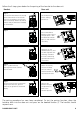
Follow the 5 steps given below for the pairing of the handset to the door unit. Handset Step 1 Press and hold the buttons (8) and (9) at the same time for a few seconds to put on the handset. You will now hear a short beep. Release (8) and (9) buttons and you will hear a 2nd beep as confirmation. Door unit Set the dipswitch 3 on the ‘Pairing’ position (7). Step 2 Place 4 AA-alkaline batteries, keep in mind the right poles + and -. The doorbell indicator light (2) shall now burn constantly.
If after you have logged on and you hear interference coming from other wireless devices in the neighbourhood, such as a mobile phone, then repeat the above mentioned procedure or switch over to another channel (when you change the channels, you will need to repeat the pairing procedure). When the pairing has not been successful (the ‘P’ symbol on the LCD screen will flicker), then put off the handset and disconnect the power supply of the door unit by removing the batteries. Repeat the pairing procedure. 4.
5. INSTALLING THE DOOR UNIT • Decide the best place for the installation of the door unit. The attachment surface should be as flat as possible; otherwise the unit will not fit properly onto the wall plate. • It is advisable not to install the unit onto a metal surface or near other possible sources of interference, which could have negative influence on the system. • Mark the spots to drill holes at, by making use of the holes in the plate, as shown in figure 4, and attach the plate to the wall.
The electric door opener can be connected directly to the door unit of the Doorphone120 system (A,C); in this case the door opener is supplied by the door unit. Maximum load 12V/1A (additionally supplied power adapter 12VDC/600mA). > See the specifications of your electric door opener, to choose the socket and power supply. Max. 12V/1A (12V/600mA supplied). Max. 12V/1A 5.
LCD Icons Light up constantly - flickering Icon Status Icon Status Someone is at the front door Ringtone and vibration selected Someone is at the back door Illumination and vibration selected Missed call Ringtone, illumination and vibration Out of range Door opener Line busy Battery low external unit Ringtone selected Battery low handset Bell illumination selected Battery level Vibration function selected Volume Ringtone and illumination selected 6.
• As soon as the handset is answered, the door unit doorbell indicator light (2) shall burn constantly. The caller can communicate by speaking into the microphone (3). To prevent echo, there is a hands-free function built in, which makes sure that when a visitor speaks into the microphone (3) of the door unit, the loudspeaker (4) shuts off.
• Battery life; when used normally, the batteries of the door unit should last approximately 5-6 months. This depends on the use of the system. When the batteries are low, the symbol shall appear on the display and a signal will be heard. Pressing the on/off button (8) will stop the signal temporarily, but the symbol will remain displayed. • Outside temperature; The outside temperature is displayed on the handset.
Range is reducing • There are too many interfering sources (e.g. metal constructions) between the handset and the door unit. Place the handset at a different place for a stronger signal. • The batteries are low. Replace the door unit batteries or charge the handset. Out of reach indicator is always on • The door unit is not getting powered. Replace the batteries or check the power adapter of the door unit. • The back door on/off select dipswitch (21) is set on the ‘ON’ position. Set the dipswitch on ‘OFF’.
Power adapter Frequency Power consumption Material Connection Ambient temperature: IP value Dimensions 12 VDC, 600mA (supplied) 863-865Mhz Stand-by 2 mA Active 160 mA ABS / PC / Aluminium External power 8-12V MAX 1A Make connection 8-12V MAX 1A Break connection 8-12V MAX 1A AUX connector MAX 12V/200mA - 10° C to + 60° C IP54 150x158x35mm 11. OPTIONAL ACCESSORIES Extra handset; article no. 09739. You can link more handsets to one door unit.