AWM2P™ AWM2P MICROMODULE USER MANUAL 20262 / 20101011 • AWM2P TM © ALL RIGHTS RESERVED MARMITEK® 3
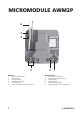
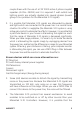
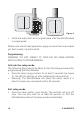
MICROMODULE AWM2P 6 5 4 3 ENGLISH 1. Phase clamp (230V) 2. Load clamp 3. Neutral clamps 4. Indicator light (LED) 5. Set up button 6. Wire connections to wall switches 2 2 1 NEDERLANDS 1. Fase aansluiting (230V) 2. Aansluiting voor belasting 3. Nulklemmen LED indicator 4. 5. Programmeerknopje 6.
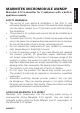
Marmitek X-10 transmitter for 2 addresses with a built-in appliance module. SAFETY WARNINGS • The wiring of your electrical installation is live (230 V) and extremely dangerous. Never connect the module when plugged into the mains. Always turn off the main switch before starting the installation. • This product is for professional use and should be installed by a certified installer. • To prevent short circuits, this product should only be used inside and only in dry spaces.
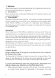
1. Modules These components will receive Marmitek X-10 signals and will switch or dim the attached lamp or appliance. 2. Controllers These components will transmit Marmitek X-10 signals and thus will control the Modules. 3. Transmitters Wireless components like remotes. The signals of these components will be received by a controller with transceiver functionality (IRRF 7243, TM13, CM15Pro or console of a Marmitek SecuritySystem).
2. It is possible that Marmitek X-10 signals are attenuated by devices and lights which are connected to the power line. In a normal home situation this effect is negligible (the Marmitek X-10 system is using active gain control to eliminate the effects). However, it is possible that a particular device in your house is attenuating the signals so much that the range of Marmitek X-10 signals is decreased significantly.
Marmitek X-10 signals are disturbed by e.g. baby phones which are in TALK mode (continuous transmission). When these kind of signals are present on the power line it is possible that the Marmitek X-10 signals will not come through. 5. The mains do not stop at the front door of your home. Everything that is attached to mains nearby your home can have influence on Marmitek X-10 signals (e.g. heavy machinery).
• • • The AWM2P supports two way Marmitek X-10 communication. Both normal switches (on-off) and Momentary switches can be connected to the module. These are automatically recognized by the AWM2P. This module is suitable for installing two-way switches without wiring between the switches (MicroModules pass on their status to other MicroModules). The AWM2P can control Macro’s/Scenario’s by operating a conventional switch (with for instance Marmitek ActiveHomePro).
White: Input 2, second address When the red wire is connected to the phase wire, the programmed “address +1” will be transmitted (e.g. when A3 is programmed as the base address then the Marmitek X-10 address A4 will be sent by using input 2). If the status in the MicroModule was ON, an OFF command will be transmitted. If the status in the MicroModule was OFF, an ON command will be transmitted.
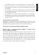
ENGLISH PROG. AWM2P white Purple N L Brown (L) Black Blue (N) P Brown (L) Figure 2 • • Connect the phase, neutralize and load wire to the terminals of the MicroModule AWM2P. Connect the thin wires of the built-in module to the wall switch. Connect the phase wire to clamp P of the wall switch. P PROG. AWM2P N L Figure 3 • • Position the MicroModule against the back wall of the wall outlet behind all the wires. You are now able to program the MicroModule.
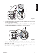
prog. prog. SAIX SAIX Figure 4 • Install the wall switch at its original place after the MicroModule is programmed. Please note: due to heat generation, apply no more than one module per flush socket / central socket! Programming WARNING: DO NOT FORGET TO TURN ON THE MAIN MASTER SWITCH PRIOR TO PROGRAMMING. Activate the setup mode. The following steps have to be taken to start the setup procedure for programming the MicroModule: • Press the setup (prog.) button for at least 3 seconds (see figure 5).
ENGLISH P PROG. AWM2P N L PROG. Figure 5 Activate or exit the setup mode.
program the preferred settings (When you use an RF remote control like the Marmitek 8-in-1, then a TM13 Plug-in Transceiver is required to convert the RF signals to the X-10 commands on the power line). Example 1. Program the Marmitek X-10 address E4: • Setup your remote control (see manual 8-in-1) and the TM13 transceiver to house code E. • Start with the MicroModule in setup mode. • Press the Marmitek X-10 button (marked with the symbol of a house) of the 8-in-1 remote control and then press button 4.
An AWM2P cannot send ALL LIGHTS ON or ALL UNITS OFF signals for the second address itself. It can only receive this signal and based on this signal, adjust its internal status. FREQENTLY ASKED QUESTIONS What is the reason for modules to switch on/off spontaneously? It is possible that a Marmitek X-10 System is installed at one of your neighbours using the same House Code. To solve this problem try to change the House Code of your system, or have FD10 Phase Coupler/ Filter installed at your incoming mains.
when the range of your remotes is not sufficient. The TM13 is using so called collision detection to prevent signals to be disturbed when more than one TM13 is transmitting. TM13’s will wait for a quite power line before transmitting their data. To prevent your Marmitek X-10 System to become slow or to prevent dimming from becoming less smooth, make sure that the TM13 units are placed as far away from each other as possible.
AWM2P™ 15 ENGLISH Environmental Information for Customers in the European Union European Directive 2002/96/EC requires that the equipment bearing this symbol on the product and/or its packaging must not be disposed of with unsorted municipal waste. The symbol indicates that this product should be disposed of separately from regular household waste streams.
Copyrights Marmitek is a trademark of Marmidenko B.V. AWM2P is a trademark of Marmitek B.V. All rights reserved. Copyright and all other proprietary rights in the content (including but not limited to model numbers, software, audio, video, text and photographs) rests with Marmitek B.V. Any use of the Content, but without limitation, distribution, reproduction, modification, display or transmission without the prior written consent of Marmitek is strictly prohibited.
DECLARATION OF CONFORMITY Hereby, Marmitek BV, declares that this AWM2P is in compliance with the essential requirements and other relevant provisions of the following Directives: DIRECTIVE 2004/108/EC OF THE EUROPEAN PARLIAMENT AND OF THE COUNCIL of 15 December 2004 on the approximation of the laws of the Member States relating to electromagnetic compatibility Directive 2006/95/EC of the European Parliament and of the Council of 12 December 2006 on the harmonisation of the laws of Member States relating to