™ IP EYE ANYWHERE P EYE ANYWHER IP EYE ANYWHERE 241/341 Advanced Installation Guide 20377 / 20110202 • IP EYE ANYWHERE 241/341™ ALL RIGHTS RESERVED MARMITEK ©
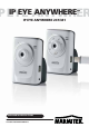
Preface Thank you for purchasing the Marmitek H.264/MPEG4/MJPEG Day&Night or True Colour Megapixel Network Camera, a standalone system that can be connected directly to an Ethernet or Fast Ethernet network. Equipped with a megapixel CMOS sensor, the camera allows you to capture a wider field of view with a resolution of up to 1280 x 1024. With support for latest H.264 technology, you can record streaming video that utilizes high quality H.
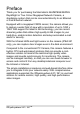
This Advanced Installation Guide provides you with the instructions and illustrations on how to use your camera, which includes: Chapter 1 Introduction to Your Camera describes the features of the camera. You will also know the components and functions of the camera. Chapter 2 Hardware Installation helps you install the camera according to your application environment. You can use this camera at home, at work, at any where you want.
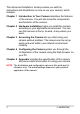
Contents C H A P T E R 1 ............................................................................................ 5 INTRODUCTION TO YOUR CAMERA ............................................................... 5 1.1 1.2 1.3 1.4 CHECKING THE PACKAGE CONTENTS ...................................5 GETTING TO KNOW YOUR CAMERA......................................6 FEATURES AND BENEFITS ...................................................10 SYSTEM REQUIREMENT....................................................
SAFETY WARNINGS • To prevent short circuits, this product should only be used inside and only in dry spaces. • Do not expose the components to rain or moisture. Do not use the product close to a bath, swimming pool etc. • Do not expose the components of your systems to extremely high temperatures or bright light sources. • In case of improper usage or if you have altered and repaired the product yourself, all guarantees expire.
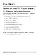
C HAPTER 1 INTRODUCTION TO YOUR CAMERA 1.1 Checking the Package Contents Check the items contained in the package carefully. You should have the following: 5 One IPEyeAnywhere 241 / 341 Network Camera 5 One AC Power Adapter 5 One Camera Stand 5 One External Antenna 5 One Ethernet Cable (RJ-45 type) 5 One Installation CD-ROM 5 One Quick Installation Guide NOTE Once any item contained is damaged or missing, contact the authorized dealer of your locale.
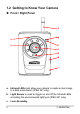
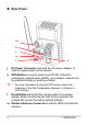
1.2 Getting to Know Your Camera Front / Right Panel h e a g f c b d i a. Infrared LEDs (x6) allow your camera to capture clear image in a dark environment (IPEA 241 only). b. Light Sensor is used to trigger on and off the Infrared LEDs according the environmental light level.(IPEA 241 only) c.
d. USB Port allows you to connect an external USB device. It provides the power distribution up to 500mA. e. Internal Microphone allows the camera to receive sound and voice. f. Link LED indicates the camera’s network connectivity with the flashing green light. g. Power LED indicates the camera is powered on with the steady amber light. h. External Antenna i. USB* Unmount Button Is used to remove the connected USB device safely.
Rear Panel m k j o l j. n DC Power Connector connects the AC power adapter, in order to supply power to the camera. k. WPS Button is used to protect your WLAN. Instead of entering the network name (SSID), your wireless network can be protected simply by pushing a button. TIP For more information of using the WPS button, refer to the instruction of the Web Configuration, Network >> Wireless >> WPS Setting. l.
n. Ethernet Cable Connector connects the network cable, which supports the NWay protocol so that the camera can detect the network speed automatically. o. Audio-out Connector connects an external active speaker.
1.3 Features and Benefits z H.264/MPEG4/MJPEG Multi-codec Supported The IPEyeAnywhere 241 / 341provides you with excellent images by the H.264/MPEG4/ MJPEG multi-codec selectable technology, allowing you to adjust image size and quality, and bit rate according to the networking environment. z High Resolution Surveillance Equipped with a megapixel CMOS sensor, the high performance camera is designed for your professional surveillance and security applications. The image resolution is up to 1280 x 1024.
z Multiple Profiles Supported The camera supports multiple profiles simultaneously, so that you can separately set up different image settings (such as image quality and frame rate) for the video types of the camera: H.264, MPEG4, MJPEG, and 3GPP. z Flexible Audio Capability The built-in microphone of the Marmitek IP EyeAnywhere 241 / 341 camera provides on-the-spot audio via the Internet, allowing you to monitor the on-site voice.
z z z 12 Mobile Device Viewing Supported The camera supports real time video viewing on your mobile device. After installing the required software applications, you can easily monitor the camera’s real-time video from your iPhone, iPod Touch, or iPad (requires iPhone OS 3.1 or later). The latest Android phone can be supported too. Multiple Platforms Supported The camera supports multiple network protocols, including TCP/IP, SMTP e-mail, HTTP, and other Internet related protocols.
1.4 System Requirement z z Networking o LAN: 10Base-T Ethernet or 100Base-TX Fast Ethernet; Auto-MDIX. o WLAN: IEEE 802.11b/g/n Accessing the Camera using Web Browser o Platform: Microsoft® Windows® XP/Vista/WIN 7/8 o CPU: Intel Pentium III 800MHz or above o RAM: 512MB o Resolution: 800 x 600 or above o User Interface: Microsoft® Internet Explorer 6.0 or above; Apple Safari 2 or above; Mozilla Firefox 2.
C HAPTER 2 HARDWARE INSTALLATION 2.1 Installing the Camera Stand The Marmitek IP Eye Anywhere camera comes with a camera stand, which uses a swivel ball screw head to lock to the camera’s screw hole. When the camera stand is attached, you can place the camera anywhere by mounting the camera through the three screw holes located in the base of the camera stand.
2.2 Connecting the Camera to LAN/WLAN Use the provided Ethernet cable to connect the Marmitek IP Eye Anywhere camera to your local area network (LAN). When you connect the AC power adapter, the camera is powered on automatically. You can verify the power status from the Power LED on the front panel of the camera. Once connected, the Link LED starts flashing green light and the camera is on standby and ready for use now.
2.3 Applications of the Camera The camera can be applied in multiple applications, including: z Monitor local and remote places and objects via Internet or Intranet. z Capture still images and video clips remotely. z Upload images or send email messages with the still images attached. The following diagram explains one of the typical applications for your camera and provides a basic example for installing the camera.
C HAPTER 3 ACCESSING THE CAMERA 3.1 Using IPFinder The camera comes with a conveniently utility, IPFinder, which is included in the Installation CD-ROM, allowing you to search the camera on your network easily. 1. Insert the Installation CD-ROM into your computer’s CD-ROM drive to initiate the Auto-Run program. 2. Click the IPFinder item to launch the utility. The control panel will appear as below. Display the connected camera(s). Double click to link the Camera.
3.2 Accessing to the Camera Whenever you want to access the camera: 1. Since the default configuration of the camera is DHCP mode enabled, you are recommended to launch IPFinder to search the IP address that is assigned to the camera by the DHCP server, and then click Link to access the camera via the Web browser. 2. If Network Camera can't get IP Address under DHCP mode, the default IP Address will be 192.168.0.30. 3.
After you login into the Web Configuration of the camera, the Main screen will appear as below: \ X Y Z [ The Main screen of the Web Configuration provides you with many useful information and functions, including: X Live View/Setup Switch: z Click the button to configure the camera. For details, see Chapter 4. button to return to the Main z Click the screen to view the live view image. Y Compression Buttons: Select to transmit and record the video using H.264, MPEG4 or MJPEG compression.
Z Function Buttons: Use these buttons to control the audio, video, and trigger functions. z Manual Record allows you to record and save a video clip. z Snapshot allows you to capture and save a still image. z Browse allows you to assign the destination folder to store the video clips and still images. z Talk allows you to speak out through the camera. Please note only one user is allowed to use this function at a time. z Listen allows you to receive the on-site sound and voice from the camera.
3.3 Configuring the IP Address of the PC If you are failed to access to the camera, please check the IP address of your computer. When you connect the camera to your computer directly to proceed with configuration of the camera, you need to set up the IP addresses to be in the same segment for the two devices to communicate. 1. On your computer, click Start > Control Panel to open the Control Panel window. 2. Double-click Network Connection to open the Network Connection window. 3.
C HAPTER 4 CONFIGURING THE CAMERA 4.1 Using the Web Configuration You can access and manage the camera through the Web browser and the provided software application UltraView Pro. This chapter describes the Web Configuration, and guides you through the configuration of the camera by using the Web browser. on the Main To configure the camera, click screen of Web Configuration. The Web Configuration will start from the Basic page.
4.2 Quick Setup 4.2.1 Using Smart Wizard The camera’s Smart Wizard lets you configure your camera easily and quickly. The wizard will guide you through the necessary settings with detailed instructions on each step. To start the wizard, click Smart Wizard in the left menu bar. Step 1. Camera Settings Enter the name and location for the camera. Enter the administrator password twice.
Step 2. IP Settings Select the IP setting according to your network: DHCP, Static IP, or PPPoE.
Step 3. Email Settings Enter the required information to be able to send email with image.
Step 4. Wireless Networking Enter the required settings for wireless networking.
Step 5. Confirm Settings Click Apply to finish the wizard and reboot the camera. Click Prev to go back to the previous step(s) and change the settings; or click Cancel to end the wizard and discard the changes.
4.2.2 Using My Android The camera’s My Android wizard lets you set up your Android mobile and Google services (Google Talk and Picasa) easily and quickly. The wizard will guide you through the necessary settings with detailed instructions on each step. To start the wizard, click My Android in the left menu bar. Step 1. Setting Up Google Talk Account Enter the Google Talk account for your camera. Step 2. Setting Up Gmail Account Enter the Gmail account for your camera. Step 3.
Step 5. Confirm Settings Click Apply to finish the wizard and reboot the camera. Click Prev to go back to the previous step(s) and change the settings; or click Cancel to end the wizard and discard the changes. NOTE Once you have set your Gmail account in step 2, the Email setting in Event Server Setting will be completed automatically. For more information, refer to the instruction of the Web Configuration, Event Server Setting >> Email.
4.3 Basic Setup The Basic menu contains three sub-menus that provide the system settings for the camera, such as the Camera Name, Location, Date & Time, and User management. 4.3.1 Basic >> System z 30 Basic: This item allows you to assign the camera name and location information. - Camera Name: Enter a descriptive name for the camera, which is helpful to identify the camera easily while multiple cameras are connected within the network.
z z - Location: Enter a descriptive name for the location where is monitored by the camera. - Language Default: Select your favorite displayed language for the system. Indication LED Control: This item allows you to set the LED illumination as desired. The available options include: Normal and OFF. IR LED Control: This item allows you to control the IR LED. The available options include: Auto and OFF. When OFF is selected you can select the start and end time when the IR LEDS have to be off.
z z General User - User Name/Password: Enter the user’s name you want to add to use the camera. Then, enter the password for the new user. After entering the User Name and Password, click Add/Modify to add the new user to the camera. To modify the user’s information, select the one you want to modify from UserList and click Add/Modify. - UserList: Display the existing users of the camera. To delete a user, select the one you want to delete and click Delete.
4.4 Network Settings The Network menu contains the networking related settings for the camera, such as the IP Setting, DDNS Setting, IP Filter, and Wireless.
4.4.1 Network >> Network z IP Setting: This item allows you to select the IP address mode and set up the related configuration. The default setting is DHCP mode enabled. - DHCP: Select this option when your network uses the DHCP server. When the camera starts up, it will be assigned an IP address from the DHCP server automatically. - Static IP: Select this option to assign the IP address for the camera directly. You can use IPFinder to obtain the related setting values.
2. Select the Provider from the pull-down list. 3. Enter the required information in the Host Name, User Name, and Password boxes. NOTE You have to sign up for DDNS service with the service provider before configuring this feature. z UPnP: The camera supports UPnP (Universal Plug and Play), which is a set of computer network protocols that enable the device-to-device interoperability.
4.4.3 Network >> IP Filter The IP Filter setting allows the administrator of the camera to limit the users within a certain range of IP addresses to access the camera. To disable this feature, select the Disable option; otherwise, select the Accept option to assign the range of IP addresses that are allowed to access the camera, or select the Deny option to assign the range of IP addresses that are blocked to access the camera. z Disable: Select this option to disable the IP Filter function of the camera.
4.4.4 Network >> Wireless Setting The IPEyeAnywhere 241 / 341 supports WLAN while you use the wireless network. Select the Enable option to enable this feature. z Wireless - Network ID (SSID): Keep the default setting of this option to connect the camera to any access point under the infrastructure network mode. To connect the camera to a specified access point, set a SSID for the camera to correspond with the access point’s ESS-ID.
Click Site Survey to display the available wireless networks, so that you can easily connect to one of the listed wireless networks. List of searching results - Wireless Mode: Select the type of wireless communication for the camera: Infrastructure or Ad-Hoc. - Channel: Select the appropriate channel from the list when you use an Ad-Hoc connection. - Authentication: Select the authentication method to secure the camera from being used by unauthorized user: Open, Shared-key, WPA-PSK, and WPA2-PSK.
Encryption: Select the WEP option to enable the data encryption feature to secure the camera within the wireless network. Format: Once you enable the Encryption feature, you need to determine the encryption format by selecting ASCII or HEX. ASCII format causes each character you type to be interpreted as an eight-bit value. Hex format causes each pair of characters you type to be interpreted as an eight-bit value in hexadecimal (base 16) notation.
4.4.5 Network >> Wireless >> WPS Setting WPS (Wi-Fi Protected Setup) sets a new standard of Wi-Fi security, providing a simplified secure network setup solution for the end users. Once the required settings have been completed, your wireless network can be protected by simply pressing the WPS button on the camera. z PROTECTED SETUP: Press the Reset to Unconfigured button to reset the WPS configuration of the camera.
4.5 Setting up Video & Audio The Video & Audio menu contains four sub-menus that provide the video and audio settings for the camera. 4.5.1 Video & Audio >> Camera z Image Setting - Brightness: Adjust the brightness level from 0 ~ 100. - Saturation: Adjust the colours level from 0 ~ 100. - Sharpness: Adjust the sharpness level from 0 ~ 100. TIP Click Default then Apply to restore the default settings of the three options above.
- Light Frequency: Select the proper frequency according to the camera’s location to reduce the flicker: 50Hz, 60Hz or Outdoor. TIP When the camera is installed indoors, the Light Frequency option can be set normally (50Hz or 60Hz). However, the image of live video might be over exposure if the camera is focusing on the object outdoors. When this happens, you can set the option as Outdoor (even when the camera is installed indoors) to fix over exposure issue. 4.5.2 Video & Audio >> Video z H.
The higher setting (VGA) obtains better video quality while it uses more resource within your network. - Video Quality: Select the desired image quality from five levels: Lowest, Low, Medium, High, and Highest. - Frame Rate: Select a proper setting depending on your network status. NOTE The camera supports H.264, MPEG4 and MJPEG compression. Please note that that MJPEG mode captures the images in JPEG format, which requires higher bandwidth to view smooth video.
4.5.3 Video & Audio >> Audio z Camera Microphone In: Select the Enable option to enable the camera’s audio function, so that you can receive the on-site sound and voice from the camera. z Camera Speaker Out: Select the Enable option to enable the camera’s external speaker function, so that the connected speaker can play the sound and voice through the camera. - Volume: Set the speaker’s volume. 4.5.
Select the area 1 or 2 from the Window pull-down list, and then click Enable. You can change the size and position of the area by holding and dragging the mouse. You can also change the colour of the mask area by clicking the Colour box and then selecting the colour you want. When done, click Apply. You can see the mask area(s) on the live view image when you click Live View. 4.5.
4.6 Event Server Configuration The Event Server menu contains six sub-menus that allow you to upload images to FTP, send emails that include still images, store the images to a NAS system, send instant message, and upload the image/video to your Picasa/YouTube account. When you complete the required settings for FTP, Email, or Network Storage, click Test to test the related configuration is correct or not. Once the camera connects to the server successfully, click Apply.
4.6.1 Event Server Setting >> FTP z FTP - Host Address: Enter the IP address of the target FTP server. - Port Number: Enter the port number used for the FTP server. - User Name: Enter the user name to login into the FTP server. - Password: Enter the password to login into the FTP server. - Directory Path: Enter the destination folder for uploading the images. For example, /Test/. - Passive Mode: Select the Enable option to enable passive mode.
- Sender User Name: Enter the user name to login the mail server. - Sender Password: Enter the password to login the mail server. - Receiver #1 Email Address: Enter the first email address of the user who will receive the email. - Receiver #2 Email Address: Enter the second email address of the user who will receive the email. - Send Email With: Select the attachment type that is to be added to the email. NOTE Due to the network environment, the camera may not upload number of images that you set. 4.6.
- Encode Format: Select MPEG4 or H.264 as the encode format while recording. - File Format: Select MP4 or AVI as the file format while recording. NOTE The recorded video files in Network Storage are enclosed by MP4/AVI format without audio. 4.6.4 Event Server Setting >> Instant Message The camera supports the Jabber IM service, so that you can send an instant message once you have a Jabber account. For more information of Jabber, please visit the Jabber Website at: http://www.jabber.org/ .
4.6.5 Event Server Setting >> Picasa Setting The camera supports the Picasa upload service, so that you can send the camera’s image to your Picasa account once you have a Picasa account. z Picasa Setting - User Name: Enter your user name to login into the Picasa account. - Password: Enter the password to login into the Picasa account. - Privacy: Set the account as Public or Private. - When Storage Full: Select Stop or Recycle – Delete Oldest Folder when the storage space on the Picasa account is full. 4.
- Description: Enter a description for the uploaded video. - Keyword: Enter a keyword for the video so that the user can search the video easily. - Category: Select a category for the uploaded video. - Privacy: Set the account as Public or Private.
4.7 Motion Detect The Motion Detect menu contains the command and option that allow you to enable and set up the motion detection feature of the camera. The camera provides three detecting areas. To enable the detecting area, select Window 1/2/3 from the pulldown list, and then select Enable. When the detecting area is enabled, you can use the mouse to move the detecting area and change the area coverage. z Name: Assign a name to the detecting area.
4.8 Event Configuration The Event Config menu contains five sub-menus that provide the commands to configure event profiles. 4.8.1 Event Configuration >> General Setting z General - Snapshot/Recording Subfolder: You can assign a descriptive name for the subfolder to save the captured image/video files. Otherwise, leave this option blank to use the default setting. - Storage Recording Time Per Event: Limit the recording time while you are using the Network Storage solution.
4.8.2 Event Configuration >> Arrange Schedule Profile z Schedule Profile: This sub-menu displays the scheduled profile(s). To customize the profile, click Add and then enter a descriptive name for the profile in the prompt dialog window. After entering the profile name, click OK and the profile is added to the Schedule Profiles list. To delete the profile, select the profile in the list and click Delete. - Profile Name: Display the profile name that you select in the Schedule Profiles list.
4.8.3 Event Configuration >> Motion Detect Trigger z Motion Detect Trigger: Select the Enable option to enable the trigger function of the camera, so that you can send captured images within the detecting area to the FTP server, email receiver, or the Network Storage server, etc. You have to configure corresponding settings, such as FTP server and email server, to enable this feature. Please note that you have to configure the related settings before enabling these features.
4.9 Tools The Tools menu provides the commands that allow you to restart or reset the camera. You can also backup and restore your configuration, and upgrade the firmware for the camera. z Factory Reset: Click Reset to restore all factory default settings for the IP EyeAnywhere. z System Reboot: Click Reboot to restart the camera just like turning the device off and on. The camera configuration will be retained after rebooting.
- Backup: Click Get the backup file to save the current configuration of the camera. - Restore: Click Browse to locate the backup file and then click Restore. z NOTE Update Firmware: You can upgrade the firmware for your camera once you obtained a latest version of firmware. - Current Firmware Version: This item displays the current firmware version. - Select the firmware: Click Browse to locate the backup file and then click Update.
4.10 USB The USB menu provides the information and controls of the connected USB device. z USB Dismount: To safely remove the connected USB device, you can press the Unmount button for four seconds on the camera or click Dismount from this item. z USB Information: Display the Total space and Free space of the USB device. z USB Setting - Split By: When the file is too large to transfer smoothly, use this option to split it by selecting File Size or Recording Time.
- When Storage Full: Select Stop Recording or Recycle – Delete Oldest Folder when the storage space on the USB device is full. - Encode Format: Set the encode format of the captured image as MJPEG or H.264. - File Format: Set the file format of the recorded video as MP4 or AVI. - Upload the Recorded file to YouTube: Select the option to simultaneously upload the recorded video file to the YouTube account that you have assigned.
4.11 Information The Information menu displays the current configuration and events log of the camera. z Device Info: Display the Basic, Video & Audio, and Network settings of the camera. z System Log: The Logs table displays the events log recorded by the system.
Appendix A.1 Specification Image Sensor Sensor Resolution Min. Illumination IR blocking filter True Colour 1/4” Colour Megapixel CMOS Sensor 1280 x 1024 0,5 Lux IPEA 341 IPEA 341 System Hardware Processor ARM9 base RAM 64MB SDRAM ROM 8MB NOR Flash Power DC 12V Power Consumption 10W max. Lens Assembly Lens Type Lens Specification View Angle Night vision IPEyeAnywhere 241 / 341TM Board Lens F2.8, 4.
Video Compression Video resolution Communication LAN WLAN Protocol support Audio Input Output Codec User Interface LAN Antenna USB Port USB Dismount Reset WPS LEDs 62 H.264/MPEG4/MJPEG H.264 & MJPEG: SXGA (1280 x 1024) @ 15fps / VGA (640 x 480) @ 30fps / QVGA (320 x 240) @ 30fps / QQVGA (160 x 120) @ 30fps; MPEG4: VGA (640 x 480) @ 30fps / QVGA (320 x 240) @ 30fps / QQVGA (160 x 120) @ 30fps 10/100Mbps Fast Ethernet with AutoMDIX (for wireless model) IEEE 802.
Software OS Support Browser Software Windows XP/Vista, and Windows 7/8 Internet Explorer 6.0 or above; Apple Safari 2 or above; Mozilla Firefox 2.
A.3 Glossary of Terms NUMBERS 10BASE-T 100BASE-TX 10BASE-T is Ethernet over UTP Category III, IV, or V unshielded twisted-pair media. The two-pair twisted-media implementation of 100BASE-T is called 100BASE-TX. A ADPCM AMR Applet ASCII ARP AVI Adaptive Differential Pulse Code Modulation, a new technology improved from PCM, which encodes analog sounds to digital form.
Communication Communication has four components: sender, receiver, message, and medium. In networks, devices and application tasks and processes communicate messages to each other over media. They represent the sender and receivers. The data they send is the message. The cabling or transmission method they use is the medium. Connection In networking, two devices establish a connection to communicate with each other.
network Ethernet networks connected to each other over a geographically dispersed area. The enterprise network serves the needs of a widely distributed company and operates the company’s mission-critical applications. The most popular LAN communication technology. There are a variety of types of Ethernet, including 10Mbps (traditional Ethernet), 100Mbps (Fast Ethernet), and 1,000Mbps (Gigabit Ethernet).
numbers 0 to 9 and the letters A to F. For example, the decimal number 15 is represented as F in the hexadecimal numbering system. The hexadecimal system is useful because it can represent every byte (8 bits) as two consecutive hexadecimal digits. It is easier for humans to read hexadecimal numbers than binary numbers. I Intranet This is a private network, inside an organization or company that uses the same software you will find on the public Internet.
way of a dedicated communication line. An ISP offers the use of its dedicated communication lines to companies or individuals who can’t afford the high monthly cost for a direct connection. J JAVA Java is a programming language that is specially designed for writing programs that can be safely downloaded to your computer through the Internet without the fear of viruses.
Network NWay Protocol your network request information from the Internet, the requests are forwarded to the Internet under the router's IP address. NAT distributes the responses to the proper IP addresses within your network. A network consists of a collection of two or more devices, people, or components that communicate with each other over physical or virtual media. The most common types of network are: LAN – (local area network): Computers are in close distance to one another.
memory to the file server’s net work adapter Others are responsible for filtering information between networks and forwarding data to its destination. Still other protocols dictate how data is transferred across the medium, and how servers respond to workstation requests and vice versa. Common network protocols responsible for the presentation and formatting of data for a network operating system are the Internetwork Packet Exchange (IPX) protocol or the Internet Protocol (IP).
SMTP SNMP Station Subnet mask The Simple Mail Transfer Protocol is used for Internet mail. Simple Network Management Protocol. SNMP was designed to provide a common foundation for managing network devices. In LANs, a station consists of a device that can communicate data on the network. In FDDI, a station includes both physical nodes and addressable logical devices. Workstations, single-attach stations, dualattach stations, and concentrators are FDDI stations.
wires enclosed in an unshielded sheath. W WAN WEP Windows WPA WPA2 72 Wide-Area Network. A wide-area network consists of groups of interconnected computers that are separated by a wide distance and communicate with each other via common carrier telecommunication techniques. WEP is widely used as the basic security protocol in Wi-Fi networks, which secures data transmissions using 64-bit or 128-bit encryption. Windows is a graphical user interface for workstations that use DOS.