CONTROL 8 8 IRIRCONTROL ™ INFRARED EXTENDER SET USER MANUAL 3 GEBRAUCHSANLEITUNG 9 GUIDE UTILISATEUR 15 MODO DE EMPLEO 21 MANUALE D’ISTRUZIONE 27 GEBRUIKSAANWIJZING 33 20326 / 20091221 • IR CONTROL 8TM © ALL RIGHTS RESERVED MARMITEK ®
© MARMITEK
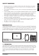
• • • • • • To prevent short circuits, this product should only be used inside and only in dry spaces. Do not expose the components to rain or moisture. Do not use the product close to a bath, swimming pool etc. Do not expose the components of your systems to extremely high temperatures or bright light sources. In case of improper usage or if you have altered and repaired the product yourself, all guarantees expire.
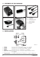
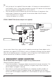
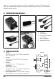
2. CONTENTS OF THE PACKAGE A B D E C A. 1 x IR Module B. 1 x IR Receiver C. 2 x IR Extension cable with 2 IR LEDs D. 1 x Power adaptor E. 1 x Manual 3. INSTALLATION 1 1 2 2 4 3 V+ G ST IR 3 4 5 1. 2. 3. 4. STATUS POWER (INPUT) (EMITTERS 1 till 4) 5. Fastening holes 4 Picture 1 Connection for a STATUS power adapter (not supplied) Connection for the POWER power adapter (supplied) Connection for max. 3 IR receiver(s) (1 x supplied) Connection for max.
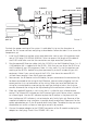
1 2 V+ G ST IR IR Receiver (Max. 3) 3 4 V+ = Orange G = Blue ST = Purple Picture 2 IR = Yellow To check the proper working of the system it is advisable first to test the formation as planned. For this reason connect everything as described as follows but don’t fix or screw the components yet. 1. Install the IR Module at a place within reach behind or next to your A/V equipment and near a 230V plug (100-240Volt 50/60Hz).
TIP: • With the help of the supplied IR Extension cables 4 A/V devices can be controlled with the IR Module, which is simply to be extended to maximal 8 A/V devices with the help of one ore two optional obtainable IR LEDs. (Art. Nr. 09777). • With the help of an extra IR Receiver you can also control your A/V equipment from another place (if desired you can extend the connection cable of the IR receiver.) - built-in IR receiver Art. nr. 08004 - built-on IR receiver Art. nr.
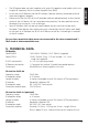
• • • The IR Receiver does not work together with some A/V apparatus and models which use a higher IR frequency like for instance Bang&Olufsen (B&O) . Ensure that the IR Receiver and the IR Extender Cable are correctly connected and that these are plugged in properly. Please ensure that the LEDs of the IR extender cable are placed correctly to the infrared sensor of the A/V device, this has to be done very precisely. The exact position can be found easily by shining at it with a flashlight.
IR Extension cable Connection: IR LEDs: Length of cable: 3.5mm jack plug 2x IR LED 3 metres (from plug to division 2m, from division to LED 1m). 6. OPTIONAL ACCESSORIES Extra IR receiver Built-on Art.nr. : 08003 Panel Mount Art.nr.: 08004 With the help of an extra IR Receiver you can also operate your A/V from another room. See for more information www.marmitek.com. 08003 Extra IR Extension cable Art.nr.: 09777 With the help of an extra IR extension cable you can operate 2 extra A/V devices.
• • • • • • Um Kurzschluss vorzubeugen, dieses Produkt bitte ausschließlich innerhalb des Hauses und nur in trockenen Räumen nutzen. Setzen Sie die Komponenten nicht Regen oder Feuchtigkeit aus. Nicht neben oder nahe eines Bades, Schwimmbades usw. verwenden. Setzen Sie die Komponente Ihres Systems nicht extrem hohen Temperaturen oder starken Lichtquellen aus. Bei einer zweckwidrigen Verwendung, selbst angebrachten Veränderungen oder selbst ausgeführten Reparaturen verfallen alle Garantiebestimmungen.
werden eins zu eins an alle angeschlossenen IR LED weitergegeben. Wenn der IR Empfänger ein IR Signal Ihrer Fernbedienung empfängt, so wird diese aufleuchten sodass Sie das System auf korrekten Betrieb kontrollieren können. 2. VERPACKUNGSINHALT A B D E C A 1x IR Modul B 1x IR Empfänger C 2x IR Verlängerungskabel mit 2 IR LED D 1x Speisungsadapter E 1x Gebrauchsanleitung 3. INSTALLATION 1. 2. 3. 4. 5. 10 STATUS Anschluss für einen STATUS Speisungsadapter (nicht mitgeliefert).
IR LED (Max. 4 IR-Verlängerungskabels) IR Modul 1 2 3 DEUTSCH V+ G ST IR 4 V+ = Orange IR Empfänger (Max. 3) G = Blau ST = Lila IR = Gelb Abbildung 2 Zur Kontrolle des korrekten Systembetriebs empfehlen wir, die von Ihnen geplante Aufstellung zunächst zu testen. Schließen Sie dazu alles an, wie im Nachfolgenden umschrieben, kleben oder schrauben Sie die Komponenten jedoch noch nicht fest. 1.
TIPP: • Mit dem IR Modul können mithilfe des mitgelieferten IR Verlängerungskabels 4 A/V Geräte bedient werden. Diese können mit 1 oder 2 optional erhältlichem IR LEDs kinderlicht auf bis zu max. 8 A/V Geräte erweitert werden, (Art.-Nr. 09777). • Mithilfe eines zusätzlichen IR Empfängers können Sie Ihre A/V Geräte auch von einem anderen Ort aus bedienen (Sie können dazu den Anschlussdraht des IR Empfängers nach Wunsch verlängern). - Einbau IR Empfänger Art.-Nr. 08004 - Aufbau IR Empfänger Art.-Nr.
• • • Sie haben Fragen, die hier nicht beantwortet wurden? Klicken Sie dann auf www.marmitek.com. 5. TECHNISCHE DATEN IR Modul Speisung POWER: Speisung STATUS: IR LED Anschlüsse: IR Empfänger Anschluss: Abmessungen: 100-240VAC 50/60Hz, 12VC 500mA (mit enthalten). 12VDC 200mA. Stecker, - 5.5mm außen / + 2.1mm innen (nicht mit enthalten). 4x 3,5mm Mini-Jack (Mono). 1 Connector für max. 3 parallel angeschlossene Empfänger. 85x49x24mm (einschließlich Befestigungspunkte).
IR Verlängerungskabel Anschluss: 3,5mm Mini-Jack. IR LED 2x IR LED Kabellänge: 3 Meter (von Stecker bis Teilung 2m, von Teilung bis LED 1m). 6. OPTIONAL ERHÄLTLICH Extra IR Empfänger Aufbau Art.-Nr.: 08003 Einbau Art.-Nr.: 08004 Mithilfe eines zusätzlichen IR Empfängers können Sie Ihre A/V Geräte auch von anderen Räumen aus bedienen. Weitere Informationen zu diesem Thema finden Sie unter www.marmitek.com. 08003 08004 Extra IR Verlängerungskabel Art.-Nr.
• • • • • • Afin d’éviter un court-circuit, ce produit ne doit être utilisé qu’à l’intérieur, et uniquement dans des endroits secs. Ne pas exposer les composants à la pluie ou à l’humidité. Ne pas utiliser à côté de ou près d’une baignoire, une piscine, etc. Ne pas exposer les composants de votre système à des températures extrêmement élevées ou à des sources de lumières trop fortes. Toute utilisation impropre, toute modification ou réparation effectuée vous-même annule la garantie.
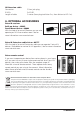
2. LE CONTENU DE L’EMBALLAGE A B D E 3. L’INSTALLATION C A 1x Module IR B 1x Récepteur IR C 2x Rallonge IR avec 2 IR LED’s D 1x Adapteur d’alimentation E 1x Mode d’emploi le Module IR 1. STATUT/STATUS Raccordement statut pour un adapteur 1 1 d’alimentation (non fournie). 2 2. PUISSANCE/POWER 2 Raccordement pour la puissance de l’adapteur 4 d’alimentation (fournie). 3 V+ 3. (INPUT) G 3 Raccordement pour max. 3 récepteur(s) IR (1x ST 4 IR fournie). 4.
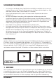
IR LEDs (Max. 4 Câbles extension IR) le Module IR 1 2 V+ G ST IR IR Récepteur (Max. 3) V+ = Orange G 3 4 Représentation 2 = Bleu ST = Violet 1. 2. 3. 4. 5. Montez le Module IR à un endroit que vous pouvez atteindre facilement, derrière ou à côté de vos appareils A/V, et dans le voisinage d’une prise de courant (100-240Volt 50/60Hz). Tenez compte de la longueur des fils de l’IR LED’s et faites en sorte que les raccordements restent si possible accessible.
Conseil : • Avec le Module IR vous pouvez, grâce aux rallonges IR qui sont fournies, servir 4 appareils A/V simultanément, vous pouvez également avec l’aide d’un ou deux LEDs IR, optionnellement disponible, agrandir simplement jusqu’au maximum de 8 appareils A/V. (Art no 09777) • Avec l’aide d’un IR récepteur extra vous pouvez également servir vos appareils A/V à partir d’un autre endroit (vous pouvez prolonger, si vous le désirez, les fils de raccordement du IR récepteur). - Récepteur IR incorporé Art nr.
• • • • dans le récepteur IR va s’illuminer à la réception d’un signal IR. Le Récepteur IR n´est pas compatible avec certain appareils A/V et modèles qui font usage d’une fréquence IR plus haute comme par exemple Bang&Olufsen (B&O) Veillez à ce que le Récepteur IR et le Câble de Rallonge IR soient correctement raccordés et entièrement insérés. Assurez-vous que les LED du câble d’extension sont collés exactement sur le capteur IR de l’appareil A/V, il s’agit d’être très précis.
Récepteur IR: Angle de réception IR: Dimensions récepteur: Câble de rallonge IR Raccordement: IR LED’s: Longueur de câbles: Indication réceptionLED. 90º (+45º/-45º depuis le centre). diamètre 15.9mm, mesure de perçage 16mm Longueur 50mm profondeur d’encastrement 55mm Épaisseur maximale des matériaux 40mm 3.5mm fiche jack 2x LED IR 3 mètres (depuis les bornes de raccordement jusqu’à la scission 2 mètres, et à partir de la scission jusqu’aux LED’s 1 mètre). 6.
AVISOS DE SEGURIDAD • • • • • • Para evitar un cortocircuito, este producto solamente se usa en casa y en habitaciones secas. No exponga los componentes del sistema a la lluvia o a la humedad. No se use cerca de una bañera, una piscina, etc. No exponga los componentes del sistema a temperaturas extremamente altas o a focos de luz fuertes. En caso de uso indebido o modificaciones y reparaciones montados por su mismo, la garantía se caducará.
2. CONTENIDO DEL EMBALAJE A B D E C A 1x Módulo IR B 1x Receptor IR C 2x Cable de extensión IR con 2 LEDs IR D 1x Adaptador de alimentación E 1x Modo de empleo 3. INSTALACION Módulo IR 1 1 2 2 4 3 V+ G ST IR 3 4 5 1. 2. 3. 4. Ilustración 1 Conexión para un adaptador de alimentación STATUS (no incluido). Conexión para un adaptador de alimentación POWER (incluido). Conexión para 3 receptores IR (como máximo) (1x incluido).
LEDs IR (Max. 4 Cables de extensión infrarrojo) Módulo IR 1 2 V+ G ST IR Receptor IR (3 máximo) V+ = Naranja G = Azul 3 4 Ilustración 2 ST = Violetta Le aconsejamos que pruebe la mejor posición para controlar el funcionamiento del sistema. Conecte todos los elementos como queda descrito abajo, pero no pegue o atornille los componentes aún. 1. Coloque el módulo IR en un sitio accesible detrás o al lado de los aparatos A/V y cerca de un enchufe de (100-240Volt 50/60Hz).
AVISO: • Con el módulo IR pueden manejarse hasta 4 aparatos por medio de los cables de extensión IR. Si utiliza un IR LEDs (opcionalmente adquirible), puede aumentar el número de aparatos A/V a manejar a 8 como máximo (no. de art. 09777). • Si emplea un receptor IR adicional, podrá manejar también los aparatos A/V desde otro lugar (el cable de conexión del receptor IR puede prolongarse). - Receptor IR montaje empotrado no. de art. 08004 - Receptor IR montaje no empotrado no. de art.
• • • Es importante que el Receptor IR y el Cable de Extensión IR estén correctamente conectados y completamente enchufados. Asegúrese que los LED del cable de extensión IR están pegados precisamente en el sensor infrarrojo del aparato A/V. Puede determinar la posición exacta por iluminar el sensor con una linterna. Algunas ventanillas IR de los set-top box o de los box sattelite son muy sensibles y fácilmente a sobrecargar.
Cable de extensión IR Conexión: LEDs IR: Longitud de cables: 3,5mm jack plug 2x LED IR 3 metros (de clavija a división 2m, de división a LED 1m) 6. TAMBIÉN A LA VENTA Receptor IR adicional. Montaje no empotrado No. de art.: 08003 Montaje empotrado No. de art.: 08004 Con un receptor IR adicional, los aparatos A/V también pueden manejarse desde otra habitación. Para más información vea también www.marmitek.com. 08003 08004 Cable de extensión IR adicional No. de art.
PRECAUZIONI DI SICUREZZA • • • • • • Per evitare il pericolo di cortocircuito utilizzare questo prodotto esclusivamente al coperto e in luoghi asciutti. Non esporre i componenti di questo prodotto a pioggia o umidità. Non utilizzare vicino alla vasca da bagno, piscina, ecc. Non esporre i componenti del sistema a temperature eccessivamente alte o a fonti intense di luce. In caso di utilizzo scorretto, di riparazioni o modifiche apportate personalmente decade qualsiasi garanzia.
LED a IR. Questi ultimi riconvertono il segnale elettrico in un segnale a IR che viene ricevuto dal sensore IR dell’apparecchio audio/video. Tutti i segnali del telecomando vengono trasmessi, uno per uno, a tutti i LED a IR collegati. Se il Ricevitore a IR riceve un segnale dal telecomando, si illumina in tal modo si può controllare il corretto funzionamento del sistema. 2. IL KIT COMPRENDRE A B D E C A. 1 x Modulo a IR B. 1 x Ricevitore a IR C. 2 x cavo di prolunga a IR con 2 LED a IR D.
LED a IR (Max. 4 Cavi di prolunga ad infrarossi) IR Modulo a IR 1 2 V+ G ST IR Ricevitore a IR (Max. 3) V+ = Arancio G = Blu 3 4 Figura 2 ST = viola Per controllare il corretto funzionamento del sistema si consiglia di testare dapprima la disposizione pianificata. A tal fine, collegare tutti i componenti come descritto di seguito, senza tuttavia applicarli o avvitarli fermamente. 1.
CONSIGLIO: • Grazie ai cavi di prolunga a IR in dotazione con il Modulo a IR si possono comandare 4 apparecchi audio/video, facilmente estendibili ad un massimo di 8 con l’ausilio del LED a IR disponibile come optional (Art nr. 09777). • Con un ulteriore Ricevitore a IR gli apparecchi audio/video si possono comandare anche da un altro luogo (è possibile allungare a piacere il cavo di connessione del Ricevitore a IR). - Ricevitore a IR da incasso Art n°. 08004 - Ricevitore a IR da appoggio Art n°.
• • • Assicurarsi che il ricevitore IR ed il cavo di prolunga IR siano collegati nel modo giusto e che siano completamente infilati. Assicurarsi che i LED del cavo di prolunga IR siano attaccati esattamente sul sensore a infrarossi del dispositivo A/V, richiede precisione! È facile trovare la posizione esatta illuminandolo con una lampadina tascabile. Alcune finestre IR dei set top box e dei box satellitari sono molto sensibili e quindi facili da sovrapilotare.
Cavo di prolunga a IR Connessione: LED a IR Lunghezza del cavo: 3,5 mm spina jack. 2x LED IR 3 metri (dalla spina sino alla biforcazione 2m, dalla biforcazione al LED 1m). 6. ACCESSORI Ricervitore a IR extra Da appoggio Art. n°: 08003 Da incasso Art. n°: 08004 Con l’ausilio di un ulteriore Ricevitore a IR è possibile comandare gli apparecchi audio/video anche da un’altro luogo. Per ulteriori informazioni consultare www.marmitek.com. 08003 08004 Cavo di prolunga a IR extra Art.
VEILIGHEIDSWAARSCHUWINGEN • • • • • • Om kortsluiting te voorkomen, dient dit product uitsluitend binnenshuis gebruikt te worden, en alleen in droge ruimten. Stel de componenten niet bloot aan regen of vocht. Niet naast of vlakbij een bad, zwembad, etc. gebruiken. Stel de componenten van uw systeem niet bloot aan extreem hoge temperaturen of sterke lichtbronnen. Bij oneigenlijk gebruik, zelf aangebrachte veranderingen of reparaties, komen alle garantiebepalingen te vervallen.
het om in een elektrisch signaal dat wordt doorgegeven aan de IR Module. Op deze module kunnen tot 8 IR LED’s worden aangesloten. Deze IR LED’s maken van het elektrisch signaal weer een IR signaal wat door de IR sensor van uw A/V apparaat wordt ontvangen. Alle signalen van uw afstandsbediening worden één op één aan alle aangesloten IR LED’s doorgegeven. Indien de IR ontvanger een IR signaal van uw afstandsbediening ontvangt zal deze oplichten zodat u het systeem kunt controleren op juiste werking. 2.
IR LEDs (Max. 4 IR verlengkabels) IR Module 1 2 V+ G ST IR 4 V+ = Oranje G = Blauw ST = Paars IR = Geel Afbeelding 2 Ter controle van de goede werking van het systeem is het raadzaam om de opstelling zoals u die hebt gepland eerst te testen. Sluit hiervoor alles aan zoals hieronder omschreven maar plak of schroef de componenten nog niet vast. 1. Monteer de IR Module op een bereikbare plaats achter of naast uw A/V apparaten, en in de buurt van een stopcontact (100-240Volt 50/60Hz).
TIP: • Met de IR Module kunnen door middel van de bijgeleverde IR Verlengkabeltjes 4 A/V apparaten worden bediend, dit is met behulp van één of twee optioneel verkrijgbare IR LEDs eenvoudig uit te breiden naar maximaal 8 A/V apparaten, (Art nr. 09777). • Met behulp van een extra IR Ontvanger kunt u uw A/V apparaten ook bedienen vanaf een andere plek (u kunt de aansluitdraad van de ontvanger desgewenst verlengen). - Inbouw IR ontvanger Art nr. 08004 - Opbouw IR ontvanger Art nr.
• • • Zorg ervoor dat de IR ontvanger en de IR verlengkabel op de juiste manier zijn aangesloten en dat deze volledig ingeplugd zijn. Zorg ervoor dat de LED’s van de IR verlengkabel precies op de infrarood sensor van het A/V apparaat geplakt zijn, dit komt zeer precies. De exacte positie kunt u eenvoudig vinden door er met een zaklamp op te schijnen. Sommige IR vensters van settop en satteliet boxen zijn zeer gevoelig en eenvoudig te oversturen.
IR Verlengkabel Aansluiting: IR LED’s Kabel lengte: 3,5mm jack plug 2x IR LED 3 Meter (van plug naar splitsing 2m, van splitsing naar LED 1m) 6. OPTIONEEL VERKRIJGBAAR Extra IR ontvanger Opbouw Artnr.: 08003 Inbouw Artnr.: 08004 Met behulp van een extra IR Ontvanger kunt u uw A/V apparaten ook bedienen vanaf een andere ruimte. Zie voor meer informatie www.marmitek.com. 08003 08004 Extra IR Verlengkabel Artnr.
DECLARATION OF CONFORMITY Hereby, Marmitek BV, declares that this IR Control 8 is in compliance with the essential requirements and other relevant provisions of the following Directives: DIRECTIVE 2004/108/EC OF THE EUROPEAN PARLIAMENT AND OF THE COUNCIL of 15 December 2004 on the approximation of the laws of the Member States relating to electromagnetic compatibility Directive 2006/95/EC of the European Parliament and of the Council of 12 December 2006 on the harmonisation of the laws of Member States rela