
Operation Manual


• The IR Receiver does not work together with some A/V apparatus and models which use
a higher IR frequency like for instance Bang&Olufsen (B&O) .
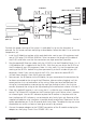
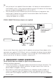
• Ensure that the IR Receiver and the IR Extender Cable are correctly connected and that
these are plugged in properly.
• Please ensure that the LEDs of the IR extender cable are placed correctly to the infrared
sensor of the A/V device, this has to be done very precisely. The exact position can be
found easily by shining at it with a flashlight.
• Some IR windows from set-top and satellite boxes are very sensitive and are easily
disrupted. These devices then receive too much infrared light and will either work badly
or not work at all. Relocate the IR LED or IR Blaster so that less infrared light is received
via the IR window.
Do you have questions that were not answered in the above mentioned ?
Then look at www.marmitek.com.
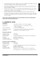
5. TECHNICAL DATA
IR Module
Feed POWER: 100-240VAC 50/60Hz, 12VC 500mA (supplied).
Feed STATUS: 12VDC 200mA. Plug, - 5.5 mm outside / + 2.1 mm
inside (not supplied).
IR LEDs connections: 4 x 3.5 mm jack plug (mono).
IR Receiver connection: 1 Connector for maximal 3 parallel connected receivers.
Dimensions: 85x49x24xmm (fastening points inclusive).
IR receiver built-on
Frequency range: 30-60 KHz.
IR reception range: ± 10 metres.
Length of cable: 4 metres, extendable to max 300 metres (UTP or equivalent).
IR receiver: Reception indication LED.
IR reception angle: 90° (+45°/-45° from centre).
Dimensions receiver bloc: 32x13x12mm.
IR receiver built-in (optional)
Frequency range: 30-60 KHz.
IR reception range: ± 10 metres
Length of cable: 2 metres, extendable to max 300 metres (UTP or equivalent).
IR receiver: Reception indication LED.
IR reception angle: 90°(+45°/-45° from centre)
Dimensions receiver: Diameter 15.9 mm - Drilling size 16 mm - Length 50 mm
Built-in depth 55 mm - Maximal thickness of material 40 mm.
7IR CONTROL 8
TM
ENGLISH